Electronic control board removal, A caution, N 1 i – Carrier 1995 Room Air User Manual
Page 6
Attention! The text in this document has been recognized automatically. To view the original document, you can use the "Original mode".
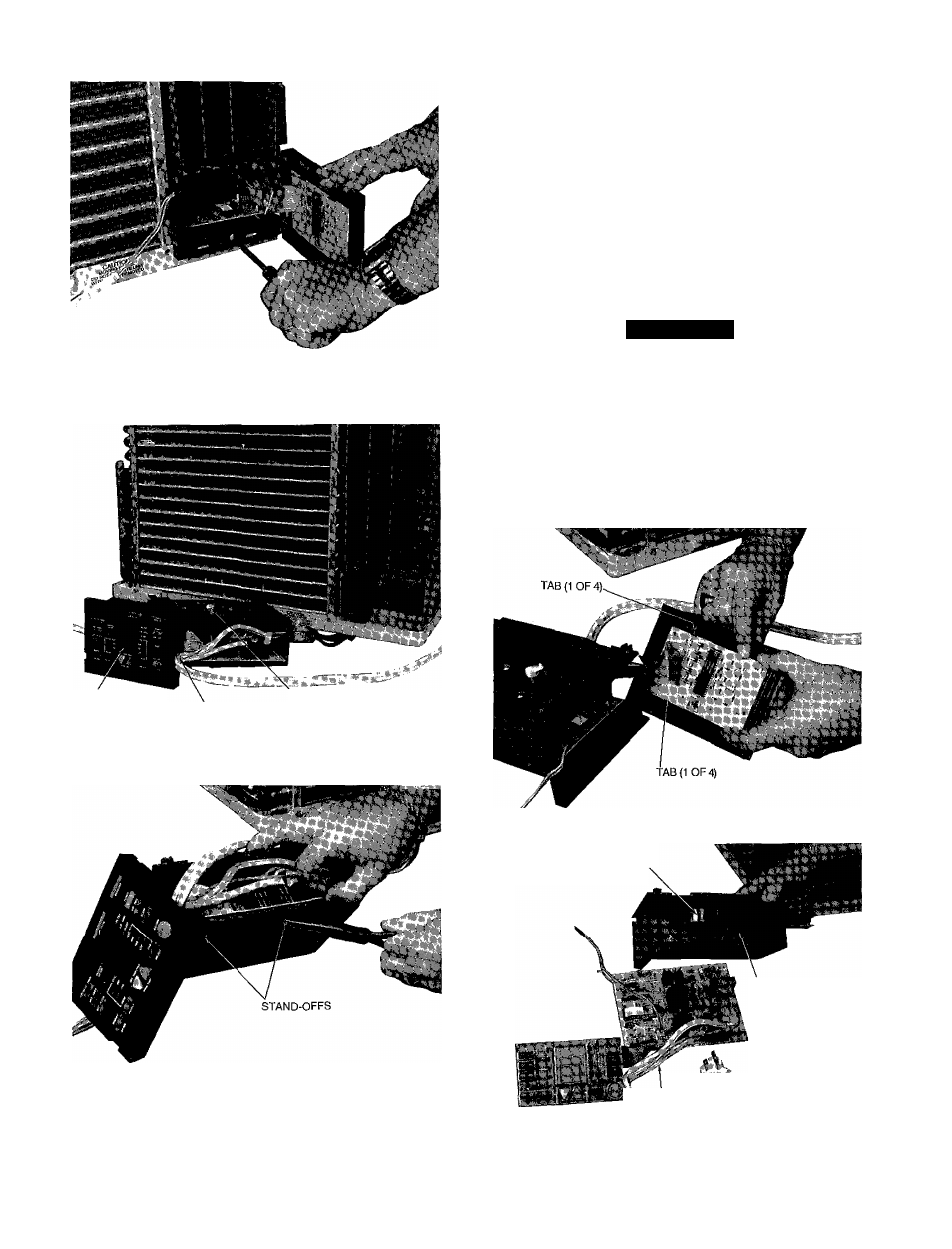
Fig. 10 — Escutcheon Piste Open
LIQUID CRYSTAL
DISPLAY (LCD)
AIR SWEEP
MOTOR CAM
WIRE TIE
Fig. 11 — Control Box Removed from Unit
Fig. 12 — Relay Board Stand-Offs
Electronic Control Board Removal
1 Remove chassis from casing See Chassis Removal in
structions, page 4
2 Remove control box See Control Box Removal instruc
tions, page 5
3 Cut wire tie holding the service cord See Fig 11
4 Gently lift tabs holding LCD (liquid crystal display) board
to rear side of escutcheon plate and lemove board See
Fig 13
5 Release pressure on relay board stand-offs (Fig 12) at
control box, lemove relay board Save stand-offs for
reassembly
6 Disconnect air sweep motor wire leads See Fig 14
A
CAUTION
When replacing electronic control board, be sure the
flying wire is attached to the 220 V voltage connection
or electronic control board will be damaged See
Fig 15
7 Attach the flying wire to the 220-V voltage connection
It is important to connect flying wire correctly or elec
tronic control board will be damaged See Fig 15
8 Reverse above procedure for reassembly
Fig. 13 - Liquid Crystal Display (LCD) Board
AIR SWEEP
MOTOR
AIR SWEEP MOTOR
WIRE LEADS
n 1
i ^
SERVICE CORD
Fig. 14 — Electronic Control Board
Removed from Control Box