Control box removal, A caution – Carrier 1995 Room Air User Manual
Page 5
Attention! The text in this document has been recognized automatically. To view the original document, you can use the "Original mode".
Control Box Removal
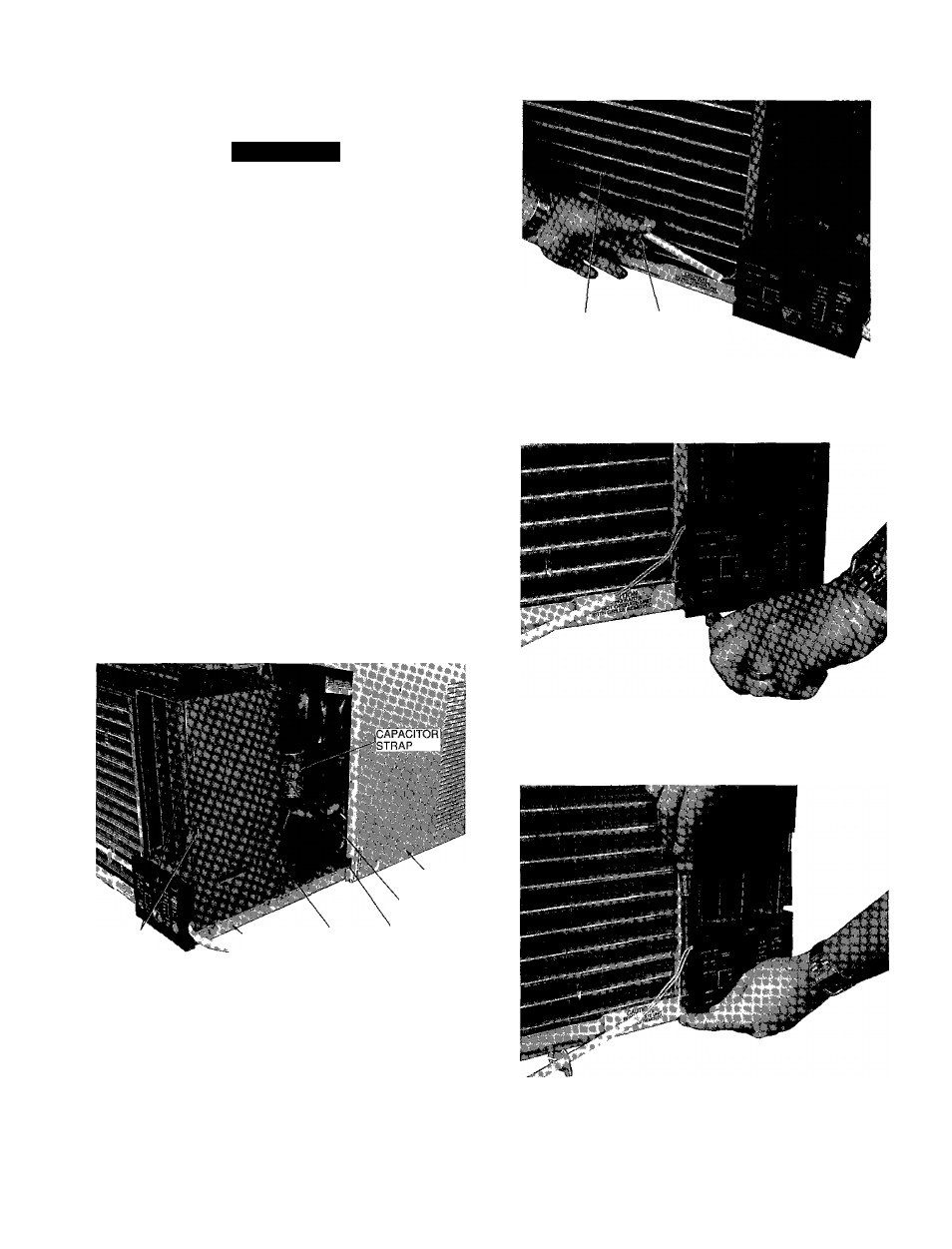
1 Remove front grille See Front Grille Removal,
page 4
A
CAUTION
Use care when sliding chassis out of casing so that chas
sis does not fall Personal injury and/or damage to the
unit and surroundings can result
NOTE Sliding chassis partly out of casing ensures that the
wiring does not become pinched when the control box is
replaced
2 Slide chassis out of casing far enough to access capac
itor located on back side of partition See Fig 6
3
Remove water seal material from wire raceway See
Fig 6
4 Remove thermistor wire retainer from evaporator coil
See Fig 7
5 Remove screw on lower left front of escutcheon plate
See Fig 8
6
Using a thin screwdriver, lift tab on left side of
escutcheon plate (Fig 9) and swing plate open See
Fig 10
7 Remove screw located in bottom center of control box
See Fig 10
8 Slide out control box, taking care to lift slightly so that
relay board stand-offs clear the basepan See Fig 11
and 12
9 Disconnect fan and compressor leads
When disassembling wiring, use numbered stickers to
identify wire lerds and terminals This aids in quick,
accurate reassembly
10
Reverse above procedure for reassembly
CASING
CAPACITOR
PARTITION
SLOTS
'CHASSIS WATER SEAL CAPACITOR
" MATERIAL STRAP SCREW
Fig. 6 — Accessing Capacitor and
Water Seal Material
EVAPORATOR
THERMISTOR WIRE
COIL
RETAINER
Fig. 7 - Removing Thermistor Wire Retainer
Fig. 8 - Removing Screw on Escutcheon Plate
Fig. 9 - Lifting Tab on Left Side of Escutcheon Plate