Propeller fan adjustment or removal (see fig. 26), Fan motor removal (see fig. 27), Propeller fan adjustment or removal – Carrier 1995 Room Air User Manual
Page 10
Attention! The text in this document has been recognized automatically. To view the original document, you can use the "Original mode".
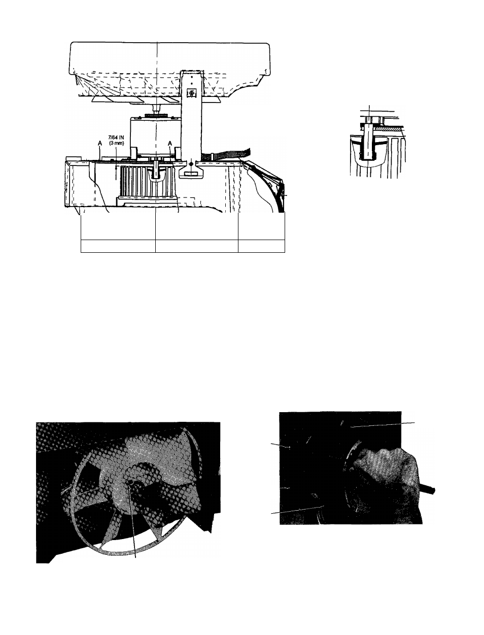
DETAILA-A
7/64 IN
(3 mm)
t '------------------------------
Ì
VI
10
1 1
Fig. 25 — Distance Between Indoor Blower Wheel and Partition for Cooling-Oniy Units
Propeller Fan Adjustment or Removal (See
Fig. 26)
1 Remove air-handling system See Air-Handling System
Removal instructions, page 7
2 Mark shaft at a point where fan hub and motor shaft
meet to aid in reassembly
3 Remove spring metal clip from fan hub See Fig 26
4 Remove fan from motor shaft
5 Reverse above procedure for reassembly
IMPORTANT When replacing fan hub, be sure to
place fan hub at the end of the motor shaft
Fan Motor Removal (See Fig. 27)
1 Remove air-handling system See Air-Handling System
Removal instructions, page 7
2
Remove indoor blower wheel and propeller fan See
Indoor Blower Wheel Adjustment or Removal and
Propeller Fan Adjustment or Removal instructions, page 9
and this page
3 Carefully disconnect fan motor wiring from plug
4
Remove 3 screws securing motor to partition See
Fig 27
5 Reverse above procedure for reassembly
SCREW
SCREW
PARTITION
SCREW
Fig. 27 - Removing Fan Motor
SPRING METAL CUP
Fig 26 -- Removing Propelier Fan
10