Carrier 50YQ User Manual
Page 8
Attention! The text in this document has been recognized automatically. To view the original document, you can use the "Original mode".
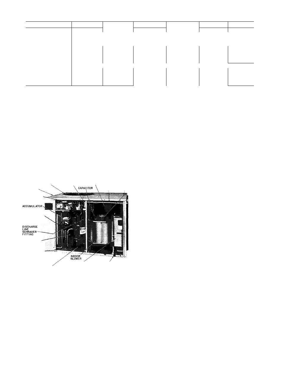
Table 4 — Service Data
UNIT 50YQ
024
030
036
042
048
060
R-22 CHARGE* (lb)
54
5 7
5 15
6 7
7 3
8 6
Refrig Control
AccuRater^M
INDOOR FAN
Centrifugal — Direct Drive — 3-Speed
Rpm
1100/1050/900
Diameter (in.)
9
9
9
10
10
10
Width (in.)
7
7
9
9
9
10
Range (cfm)
833-1040
1000-1250
1183-1480
1367-1708
1633-2040
1800-2250
Motor Hp
1/5
1/5
1/3
1/2
1/2
3/4
OUTDOOR FAN
Propeller — Direct Drive
Cfm
2500
2500
2500
2700
3200
3600
Rpm
1050
1050
1050
1050
1050
1050
Diameter (in.)
20
20
20
20
20
20
Motor Hp
1/5
1/5
1/4
1/4
1/4
1/4
"Factory refrigerant charge
Unit refrigerant system is factory charged. When
recharging is necessary, weigh in total charge indi
cated in Table 4. (Charge must be weighed in during
heating season.) Remove any refrigerant remaining
in system before recharging. If system has lost com
plete charge, evacuate system to 500 microns
(29.7 in. vacuum) before recharging. Service port
connections are provided on unit suction and dis
charge lines for evacuation and charging. (See
Fig. 10 for service port location.) Dial-a-charge
charging cylinder is an accurate device used to re
charge systems by weight. These eylinders are avail
able at refrigeration supply firms.
OUTDOOR FAN
DISCHARGE GRILL
CONTROL WIRING
TERMINAL BLOCK
TOP COVER
UNIT CONTROL
BOX
REVERSING
VALVE
\
INDOOR
INDOOR BLOWER
COIL
MOTOR I
CONTROL WIRING
CONDUIT
SUCTION LINE'
SCHRADER
FITTING
COMPRESSOR
HOLD DOWN
BOLTS
ELECTRIC
COMPRESSOR
a
I
s
EMBLY
CONDENSATE
\
DRAIN LINE LINEWIRING
SPLICE BOX
Fig. 10 — Component Location (Typical)
To check and/or adjust charge during cooling
season, use correct Cooling Cycle Charging Chart
(Fig. 11 thru 16) and follow Charging Chart Method
below. The charging chart may also be used as an
alternate method of recharging system.
To check system operation during heating cycle,
use correct Heating Cycle Operation Check Chart
(Fig. 17 thru 22). These charts indicate whether a
correct relationship exists between system operating
pressures and air temperatures entering unit. If
pressure and temperature lines do not intersect on
chart, the system refrigerant charge may not be cor
rect or other sysem abnormalities may exist. Do not
use Operation Check Charts to adjust refrigerant
charge. Weigh charge into system.
COOLING CYCLE CHARGING CHART
METHOD
1. Operate unit a minimum of 10 minutes before
checking
charge,
and
after
each
charge
adjustment.
2. Measure suction pressure by attaching a gage to
unit suction service port. (See Fig. 10 for correct
service port location.)
3. Measure outdoor (coil inlet) air dry-bulb tem
perature. Use service thermometer.
4. Using a sling psychrometer, measure wet-bulb
temperature of air entering indoor fan coil.
5. Refer to correct Charging Chart. Locate on
curves where outdoor air dry-bulb and indoor
air wet-bulb temperature lines intersect.
6. From intersect point, project vertically down
ward to chart suction pressure line. Compare
chart suction pressure to unit suction pressure
(Step 2).
7. If unit suction pressure is lower than ehart
pressure, add refrigerant to system until chart
pressure is reached. If unit suction pressure is
higher than chart pressure, remove refrigerant
until chart pressure is reached.
7 8 1