Start-up, I-r' tv – Carrier 50YQ User Manual
Page 5
Attention! The text in this document has been recognized automatically. To view the original document, you can use the "Original mode".
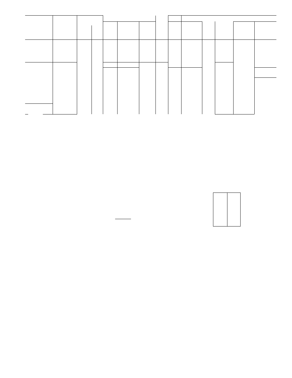
Table 2 — Unit Electrical Data (60-Hz)
i-r'
tv
OPER
COMPRESSOR
IFM
OFM
BRANCH CIRCUIT
VOLTAGE*
Min
Max
Ft
Wire
Min Gnd
Max Fuse
Min
Circuit
Amps
MODEL
V/PH
Max
Min
LRA
RLA
BCSC
FLA
FLA
Wire
Size
Wire
Size
or HACR
Type Ckt»*
(AWG)t
(AWG)t
Bkr Amps
50YQ024
66
154
—
2 4
1 3
10
48
}— -1
35
23 0
50YQ030
72
16 1
—
24
1 3
10
46
10
35
23 8
^ 50YQ036
230/1
253
207
88
18 2
—
3 6
2 1
10
38
10
45
28 5
50YQ042
94
21.0
21 2
49
1 9
8
52
10
50
33 3
50YQ048
106
25 0
27 9
49
2 2
6
71
10
60
42 0
50YQ060
208/230/1
253
187tt
150
29 2/33 4
35 3
6 4
20
4
43
6
60
52 5
50YQ042
200/3
220
180
79
146
16 6
49
20
10
55
10
40
27 6
50YQ048
87
16 9
183
49
2 2
10
48
10
45
30 0
50YQ036
200/230/3
253
180
87
12 5/11 7
—
3 6
2 1
10
74
10
30
21.3/25 3
50YQ042
230/3
253
207
g
T~
U6
143
49”
i¥~
67
id
24 7
50YQ048
70
14 8
16 4
4 9
2 2
10
58
10
40
27 6
50YQ042
460/3
506
414
35
g 3
49
1 9 ‘
14
104
14
15
12 4
50YQ048
35
7.5
8 8
4 9
2 2
14
90
12
20
14 6
50YQ042
575/3
632
518
27
49
6 8
49
1 9
14
164
14
15
11 2
50YQ048
30
60
64
49
2 2
14
141
14
15
10 9
AWG
BCSC
FLA
IFM
LRA
OFM
RLA
American Wire Gage
Branch Circuit Selection Current
Full Load Amps
Indoor Fan Motor
Locked Rotor Amps
Outdoor Fan Motor
Rated Load Amps
HACR — Heating Air Conditioning & Refrigeration
ELECTRIC HEATER INSTALLATION — For
complete heater installation data, refer to accessory
electric heater Installation, Start-Up and Service
Instructions.
GROUND LUG
(IN SPLICE BOX)
l-PHASE
CONN
TO
DISCONNECT
PER NEC
--GROUND LEAD-
Ll
L2
________________
________________
^Permissible limits of the voltage range at which units will operate
satisfactorily
tCopper wire sizes based on 60 C Use copper or copper-clad aluminum wire
only Use latest NEC for copper-clad aluminum conductor sizing
^Required when using nonmetallic conduit
“Maximum dual element fuse
ttMinimum voltage is 197 when outdoor ambient temperature exceeds
105 F
Heat Anticipator Settings for Room Thermo
stat
— Set anticipator settings for room thermostat
according to Table 3. These settings may be changed
slightly to provide a greater degree of comfort for a
particular installation.
Table 3 — Thermostat Anticipator Setting
BLK-----------(
-YEL----------
i
50YQ HEAT PUMP
GROUND LUG
(IN SPLICE BOX)
UNIT
50YQ024,
030,036,
042,048,
060
FIRST STAGE
ANTICIPATOR
SETTING
Fixed
ACCESS.
ELECTRIC
HTR (Kw)
240 V 280 V
5 0
3 75
7 5
5 6
100
7 5
15 0
11 3
20 0
150
25 0
188
27 0
22 25
SECOND STAGE
ANTICIPATOR
SETTING
-gg—
—
26
26
52
52
52
78
3-PHASE
CONN
TO
DISCONNECT
PER NEC
------ GROUND LEAD-
LI----------------------------------------------
L2-
L3
______________________________ -YPl------------------------
■ -^-BLK--
BLU-----------
i
-YEL------------ i
50YQ HEAT PUMP
_____ Field Wiring
Splice Connections
NOTE Use copper or copper-clad aluminum wire
Fig. 7 — Line Power Connections
START-UP
The 50YQ unit compressors are equipped with
crankcase heaters. It is recommended that heater be
energized a minimum of 24 hours before starting unit.
To energize heater only, set thermostat at OFF posi
tion; turn on unit main power at disconnect switch.
Accessory Outdoor Thermostat
provides adjust
able outdoor control of accessory electric heaters
of 15 Kw and over. This thermostat makes contact
when a drop in outdoor temperature occurs. It ener
gizes a stage of electric heat when the outdoor tem
perature setting is reached, provided the room
thermostat is on the second stage of heating. One
outdoor thermostat is recommended for each stage
of electric heat after the first stage. Set the outdoor
thermostat(s) progressively lower for each stage.
Refer to heat load of building and unit capacity to
determine the correct outdoor thermostat settings.
The accessory emergency heat relay is required
when 2 outdoor thermostats are used. It is auto
matically energized by the manually operated emer
gency heat switch in the indoor thermostat subhase.
The indoor thermostat locks out compressor and the
relay bypasses the outdoor thermostats for electric
heater operation during heat pump shutdown.
When one outdoor thermostat is used, an emergency
heat relay is not required. The emergency heat
switch in the indoor thermostat subbase bypasses
outdoor thermostat, locks out compressor and acti
vates electric heater.
1 8 4