Accurater™ (dual-piston type) servicing, Fig. 23 — accurater^^ (dual-piston) components – Carrier 50YQ User Manual
Page 12
Attention! The text in this document has been recognized automatically. To view the original document, you can use the "Original mode".
AccuRater™ (Dual-Piston Type) Servicing —
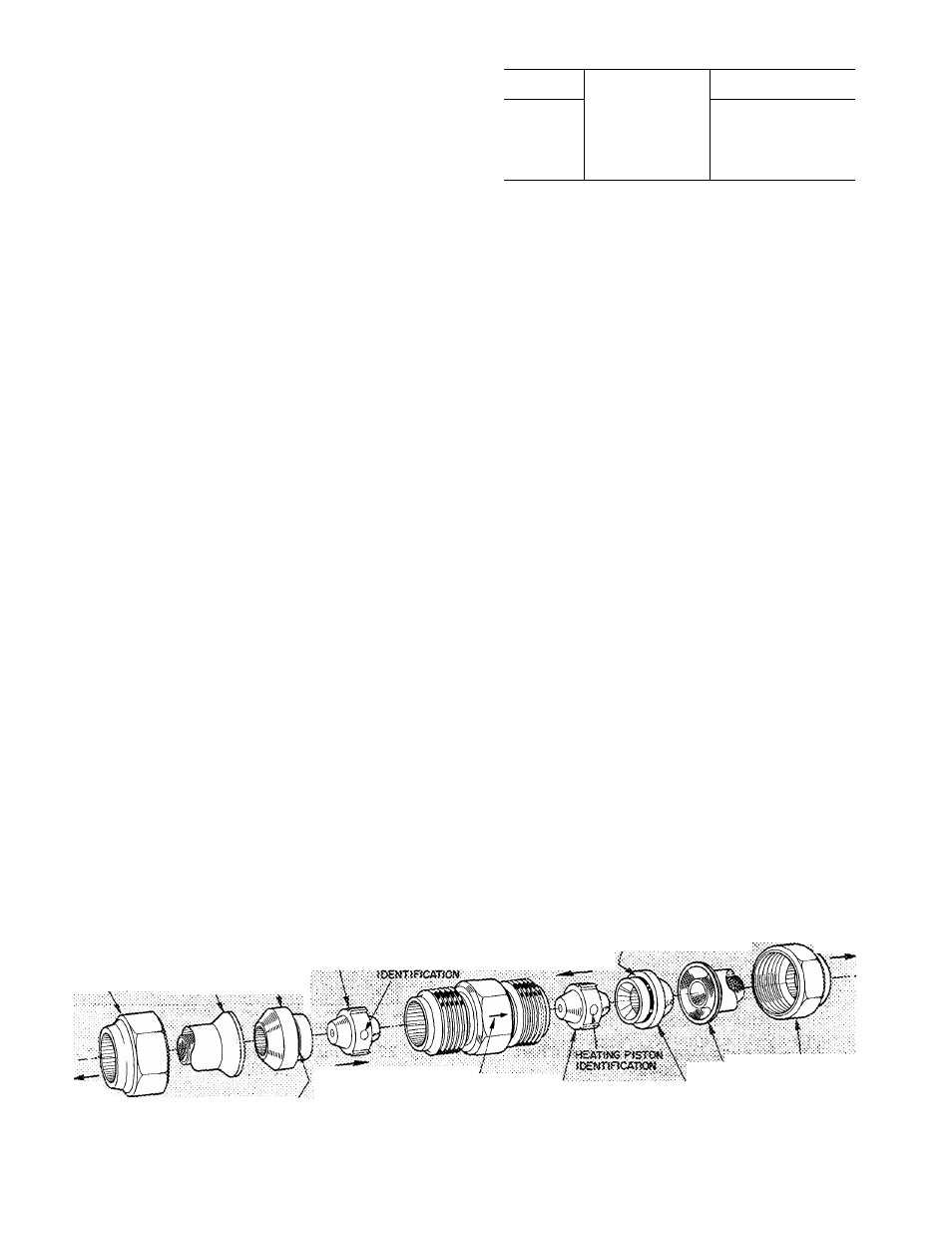
See Fig. 23 for dual-piston AccuRater components.
The pistons have a refrigerant metering orifice thru
them. The retainers form a stop for the pistons in the
refrigerant bypass mode, and a sealing surface for
liquid line flare connection. To check, clean or
replace piston;
1. Shut off power to unit.
2. Remove refrigerant from unit.
3.
Remove liquid line flare connections from
AccuRater.
4. Note position of arrow on AccuRater body with
respect to unit.
5. Pull retainer out of body. Be careful not to
scratch flare sealing surface. If retainer does not
pull out easily, carefully use vise grips to remove
retainer. Replace scratched or damaged retainer.
6. Slide piston out by inserting a small soft wire thru
metering hole (18-gage thermostat wire). See that
metering hole, sealing surface around piston
cones and fluted portion of piston are not
damaged.
7. Chart on unit access panel illustrates proper
arrangement and sizes of pistons.
8. Clean piston refrigerant metering orifice.
9. Replace container O-ring before reassembling
AccuRater.
Carrier
O-ring
part
no.
is
99CC501052.
LIQUID
LINE
STRAINERS
(protect
Accu
Rater), are made of wire mesh and located in the
liquid line on each side of the AccuRater. The
strainers are pressed into the line. Remove strainer
by threading a #10 sheet metal screw into strainer
and pulling the screw with pliers.
Compressor Removal
— See Table 5 for com
pressor information and Fig. 10 for component
location. Follow safety codes, and wear safety
glasses and work gloves. Have quenching cloth
available (step 8).
CAUTION:
ttibijag leased
ki
50 ¥Q
ccals. po xiot «yediest place excessive
Stiais iabxag
or
dasjage may result.
Table 5 — Compressor Data
MODEL
PRODUCTION
COMPRESSOR*
OIL RECHARGE (oz)
50YQ024
M24
44
50YQ030
M27
44
50Y0036
M34
44
50YQ042
P46
76
50Ya048
P53
76
50YQ060
P64
76
Refer to compressor nameplate for complete model number
1. Shut off power to unit. Remove unit access
panel. Fig. 10.
2. Remove refrigerant from unit using refrigerant
removal methods described in Carrier Standard
Service
Techniques
Manual,
Chapter
1,
Refrigerants.
3. Remove core from suction and discharge line
Schrader valves.
4. Disconnect compressor wiring at compressor
terminal box.
5. Using a tubing cutter, cut suction and discharge
lines at convenient place near compressor for
easy reassembly to new compressor with copper
clip couplings.
CAUTION: Excessive tiiovemesit of copper
Jities at compressor may cso&e a break where
Imes connect to other system componcius.
6. Remove crankcase heater from compressor
base.
7. Remove compressor hold-down bolts and lift
compressor out.
8. Carefully unbraze suction and discharge line
piping stubs from compressor. If oil vapor in
piping stubs ignites, use quenching cloth.
CAUTION: MoSkr may copiainquantity of
9.
10
.
Braze piping stubs (removed in step 8) on new
compressor.
Install new compressor in unit. Braze suction
and discharge lines to compressor piping stubs
(at points where cut, step 5) using field-supplied
copper couplings. Ensure compressor hold
down bolts are in place. Connect wiring.
fLARS
NUT
RETAiiÆR
S,TBA!Ï£B
-,
\
^
COOU^NS
PiSTON
COOUfiS PiSTON
HEATiwe
PLOW
RUЭДeЯO'Rl^4й
TO
■«DOOR
COOLfNS
P
low
RUeSERO-RlNG
STAii«PEDAf?i?OWOK
CCOPUING SOOr
(TCWAROiNDOOR COfU
PJSTO«
STRAiNER
RETAINER
PCARE
NUT
TO:
COTOOOR
cote
NOTE P«ton sizes are tabuteîed on unit access par.ef. Saainefs are îocateci >n iKjciti tine on eecti side ot AccuRater
Relative poS't'on of coccpor^er.ts is critical for ccrect operet.or.
Fig. 23 — AccuRater^^ (Dual-Piston) Components
1 2