Carrier 50YQ User Manual
Page 4
Attention! The text in this document has been recognized automatically. To view the original document, you can use the "Original mode".
g. Secure all ducts to building structure. Weather
proof duct openings in wall or roof according to
good construction practices.
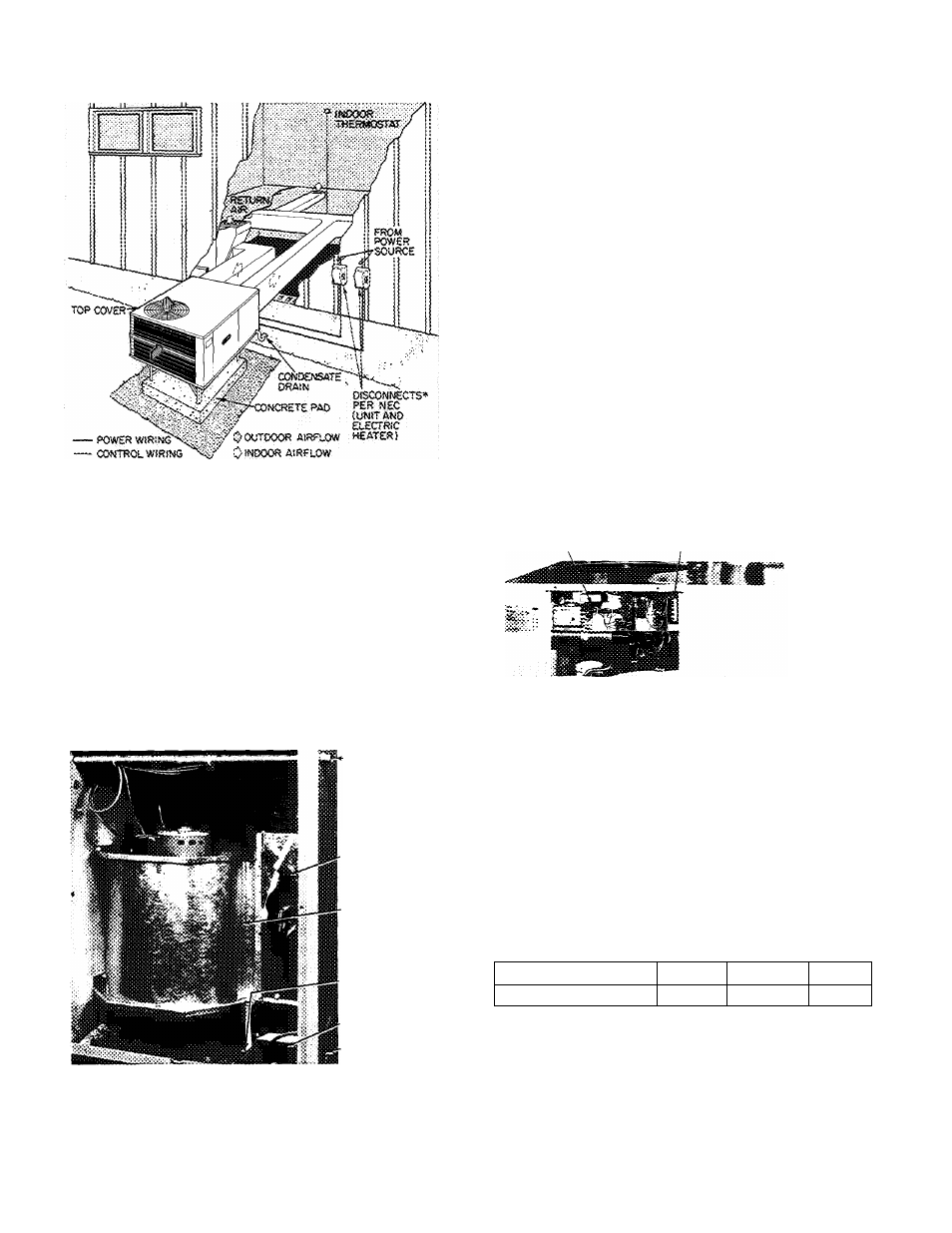
"Separate disconnect required for electric heater
> Fig. 4 — Typical Installation — 50YQ
Step 4 — Provide for Cooling Cycle Conden
sate Disposal
— Condensate may be drained
directly onto gravel apron or connected by drain
line(s) to a dry well. Follow local codes.
CONNECT DRAIN LINE to rubber condensate
drain fitting on side of unit (see Fig. 5). Use clamp
provided. Install factory-supplied condensate trap
(taped to indoor fan compartment for shipment) at
end of drain line. If a drain line is not used, connect
condensate trap to unit drain fitting as shown in
Fig. 5.
CONDENSATE
TRAP (SHIPPING
LOCATION, INSTALL
ON CONDENSATE
DRAIN LINE)
CONDENSATE
DRAIN LINE
¡i
DKO LINE
POWER
Fig. 5 — Condensate Drain and Trap Details
Step 5
—
Make Electrical Connections
— In
stall field wiring in compliance with local and
national fire, safety and electrical codes. Be sure
voltage to unit is within ± 10% of voltage indicated
on nameplate. On 3-phase units, check that phases
are balanced within 2%. Contact local power
company for correction of improper line voltage.
Oisrratton «kf tïiïÿi wth exijessm phase ¡as coiaM affect waCFaïïty, See Table 2 for recommended wire and fuse sizes. INSTALL A BRANCH CIRCUIT DISCONNECT PER NEC of adequate size to handle unit starting current. Provide a separate disconnect for unit required. (See electrie heater Installation, Start-Up and Service Instructions.) Locate disconnect(s) per Section 440-14 of National Electrical Code ROUTE LINE POWER LEADS INTO UNIT ^ provided (Fig. 1) into line wiring splice box (Fig. 6). Use copper or copper-clad aluminum wire. (Do not make connections with aluminum wire.) UNIT CONTROL WIRING TERMINAL BOX CONTROL WIRING Fig. 6 — Unit Control Box CONNECT GROUND LEAD TO GROUND LUG IN SPLICE BOX FOR SAFETY — Connect power wiring. See Fig. 7. Connect line power leads SET INDOOR FAN MOTOR SPEED — Refer to electric heater operation. Three-speed indoor fan Fan motor is equipped with spade-type speed selec tor terminals marked 1, 2 and 3. For electric heater operation, set motor at: “Low” — sizes 024 thru 042; MOTOR TERMINAL 1 2 3 FAN SPEED High Medium Low ROUTE CONTROL POWER WIRES (24-v) thru The 50YQ unit transformer supplies 24-v power for complete system including accessory electric 7 8 1
and for each accessory electric heater circuit as
within sight of and readily accessible from the unit,
(NEC).
Extend leads from disconnect per NEC thru hole
CONTROL BOX
CONDUIT,
to yellow and black pigtails on single-phase units;
yellow, blue and black pigtails on 3-phase units.
page 3 for minimum allowable air quantity for safe
motor is factory wired for high-speed operation.
“High” — size 048; “Med” — size 060.
7/8-in. conduit provided in unit. Fig. 1 and 5. Ex
tend leads to unit control wiring terminal board in
unit control box. Connect leads to terminal board
as directed in Fig. 8.
heater.