Service – Carrier 50YQ User Manual
Page 7
Attention! The text in this document has been recognized automatically. To view the original document, you can use the "Original mode".
If start thermistor is good and compressor does
not start, disconnect the thermistor from starting
circuit and give compressor a temporary capaci
tance boost as described below. Run compressor for
10 minutes, then shut off and allow system pressure
to equalize. Reconnect start thermistor and try
restarting compressor without boost capacitor. If
after 2 attempts the compressor does not start, re
move thermistor and add an accessory start capaci
tor relay package.
Single-Phase Units 50YQ024,030,036 and
042
— When supply voltage is within 10% limit
and compressor does not start, give compressor a
temporary capacitance boost.
^TEMPORARY CAPACITANCE BOOST — If
necessary, see Carrier Standard Service Techniques
Manual, Chapter 2, Electrical, for details.
WARKSNG; Cajjaciiaace boost Ls to be per-
fotaacfd írasaeá porsoKoeL improper
proce-
tlare cottjá «sose
injxtry.
SERVICE
High-Pressure Relief Valve
(Safety Control) is
located in compressor. Relief valve opens at a
pressure differential of approximately 550 psi
between suction (low side) and discharge (high side)
to allow pressure equalization.
Internal
Current
and
Temperature
Sensitive
Overload
(Safety Control) resets automatically
when internal compressor motor temperature drops
to a safe level (overloads may require up to 1 hour to
reset). When an internal overload is suspected of
being open, check by using an ohmmeter or con
tinuity tester. If necessary, refer to Carrier Standard
Service Techniques Manual, Chapter 2, Electrical,
for complete instructions.
Defrost Control,
consisting of a defrost timer,
defrost thermostat and defrost relay, interrupts
normal system heating operation to remove frost
and ice formation on outdoor coil. Frost impairs
unit performance. Defrost control simultaneously
stops outdoor fan, energizes reversing valve sole
noid to switch system into cooling cycle (outdoor
unit as condenser, indoor unit as evaporator), and
activates accessory electric heater. Unit can defrost
every 90 minutes, but will do so only if outdoor tem
peratures are in the frosting temperature zone.
For heat pump to defrost, 2 conditions are
necessary:
1. Defrost timer contacts must be closed.
2. Refrigerant temperature must be cold enough to
cause defrost thermostat contacts to close. Con
tacts close at 27 ± 3F.
Every 90 minutes of elapsed running time, the de
frost timer contacts close for 10 seconds. If the
defrost thermostat contacts are closed, the unit de
frosts. The defrost timer limits defrosting period to
10 minutes. Normally the frost is removed and the
defrost thermostat contacts will open to terminate
defrosting before 10 minutes have elapsed. Defrost
thermostat contacts open at 80 ( ± 6)F. When de
frosting is terminated, the outdoor fan motor is
energized and reversing valve solenoid is de
energized, returning unit to heating cycle.
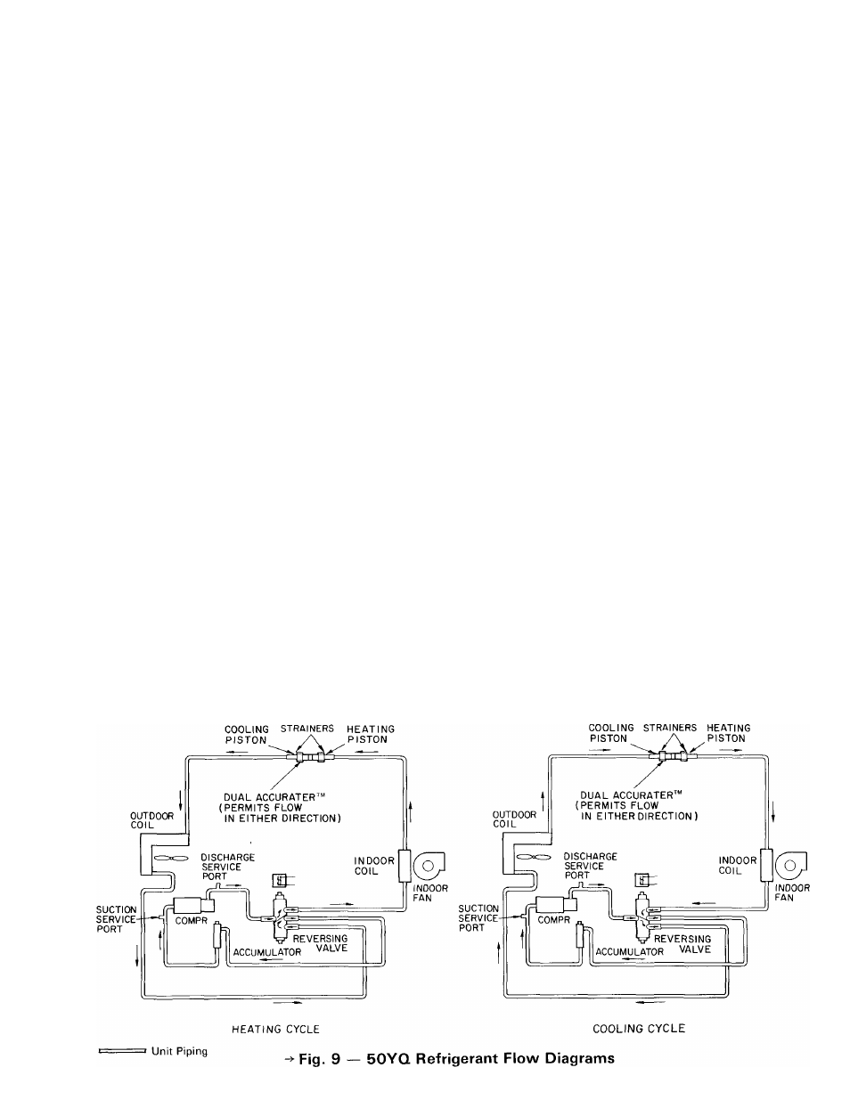
HEAT PUMP CIRCUITS shown in Fig. 9 are
refrigerant flow diagrams for heating and cooling
cycles.
> Refrigerant Charging
CAUTION: To
mcvem
personal injttxy, wear
safety
glasses
and
gloves
when
handHng
refrigerasL
Do not overcharge systemv An overcharge
can cause compressor flooding.
7 Q I