Indoor coil – Carrier 50YQ User Manual
Page 13
Attention! The text in this document has been recognized automatically. To view the original document, you can use the "Original mode".
11. Clean system. Add new suction line filter-drier
as described below.
NOTE: If a compressor failure was caused by
motor winding burnout, the by-products of the
burnout must be separated from the circulating
refrigerant. This must be done before the by
products enter the reversing valve or accumu
lator and render parts inoperative. Burnout by
products can cause future system operating
problems if left in the system.
Clean the system by installing a suction line
drier in the refrigerant line where the suction gas
enters the reversing valve. During the cooling
cycle, this is the line from the indoor coil run
ning across the top of compressor compart
ment; during heating cycle, install drier in line
between outdoor coil and reversing valve. If
possible, run unit in cooling mode when clean
ing system as installation of temporary suction
drier is simplified.
For drier installation during heating cycle, cut
vertical line below reversing valve to install
fittings and tubing as suction drier must be
placed outside of cabinet. Fabricate and install a
temporary access panel to provide protection
against entry and possible electric shock hazard.
-> To provide protection for the reversing valve,
do not place filter-drier between reversing valve
and accumulator. Since the suction drier works
on one mode only, temporarily wire the unit in
the selected mode (heating or cooling, based on
suction drier location). To insure cooling opera
tion only, install a jumper between terminals
“R” and “O” on the low voltage terminal board.
For heating operation only, remove and insulate
one of the reversing valve solenoid leads. Run
unit for 48 hours and check oil for acidity. If
satisfactory, remove suction line drier. Refer to
and follow procedure under AccuRater™ Ser
vicing for cleaning of AccuRater. Rewire unit
to normal condition.
12. Triple-evacuate and recharge unit. See Refrig
erant Charging.
Filter-Drier
— Install an accessory 50YQ900001
reversible, liquid line filter-drier assembly. Remove
dual piston AccuRater — save pistons. Cut 11 in.
from liquid line. Install flare nut on new end of line
and flare line. Install new strainers from accessory
package. Following the instructions in accessory
package, install filter-drier package components.
NOTE; Follow instructions carefully as AccuRater
piston locations are reversed from those shown
when a filter-drier is not used. On model 50YQ060,
install filter-drier and AccuRater in a vertical
position.
Lubrication
COMPRESSOR contains factory oil charge. Re
place oil when lost. See Table 5 for oil recharge. If
necessary, refer to Carrier Standard Service Tech
niques Manual, Chapter 1, Refrigerants, page 1-21,
for oil recharging procedure. Use Carrier PP33-1,
Texaco Capella B or Suniso 3G oil.
■ FAN MOTOR BEARINGS are prelubricated for 3
years heavy duty or 5 years normal duty. If oiling
holes are provided at each end of fan motor, remove
fan motor and lubricate motor with 32 drops (16
drops per hole) of SAE 10 nondetergent oil at
intervals described below;
a.
Annually, when environment is very dirty,
ambient temperature is higher than 105 F and
average unit operating time exceeds 15 hours
a day.
b. Every 3 years when environment is reasonably
clean, ambient temperature is less than 105 F and
unit operating time averages 8 to 15 hours a day.
c.
Every 5 years when environment is clean,
ambient temperature is less than 105 F and
unit operating time averages less than 8 hours
a day.
Indoor Coil
CAiniOJ?' Before petjibri33S(ng;
marntmance».
isr
tamed
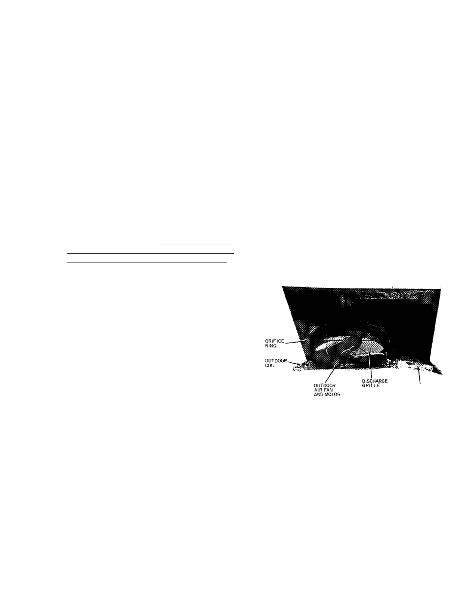
TOP COVER
INDOOR COIL
Fig. 24 — Fan, Top Cover, Coil Details
Lift or remove unit top cover for access to indoor
coil. See Fig. 24. Inspect coil periodically. Clean as
described under Outdoor Coil below.
Condensate Drain
— Clean condensate drain trap
with bottle brush; then flush condensate pan be
neath indoor coil with clean water. Ensure water
flows freely thru condensate drain.
^Indoor Fan Assembly
(Fig. 25) — Fan wheel
should be centered in fan housing. To adjust fan,
remove as follows;
1. Disconnect motor wires.
2. Remove sheet metal screws holding assembly in
place.
3. Slide entire fan assembly out of unit.
4. Loosen setscrew securing wheel to motor shaft.
5. Adjust wheel and tighten setscrew.