Control, Wt» access &msjs, Mnotutcpimz – Carrier 50YQ User Manual
Page 2
Attention! The text in this document has been recognized automatically. To view the original document, you can use the "Original mode".
■g CONDUIT
CONTROL-*“»
WIRING
0
'-6
j
3^
If DKO
ELECTRIC^
HEAT X
l| DKO
LINE
WIRING'
CONN
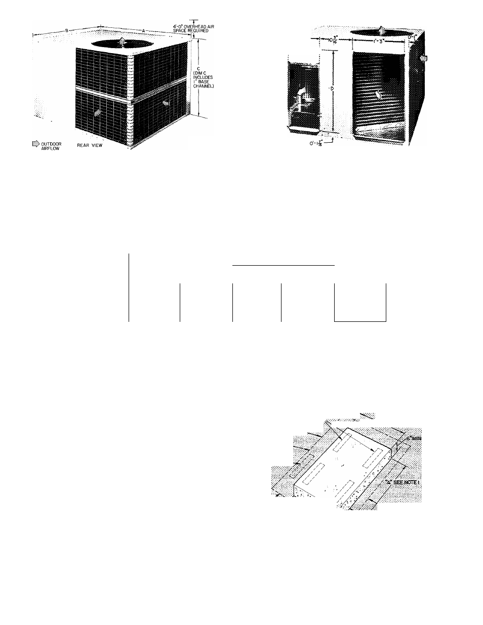
Fig. 1
L> INDOOR AIRFLOW
^ OUTDOOR AIRFLOW
RIGHT SIDE VIEW
Ceitified dimension drawings available on request
Dimensions and Connections
Table 1 — Installation Data (See Fig. 1)
UNIT
OPER WEIGHT (lb)
d
T
me
N
s
T
o
NS (ft-in )
A
B
50YQ024
303
50YQ030
320
50YQ036
333
50YQ042
375
50YQ048
417
50YQ060
4-0-7/16
3-6-1/4
C'
1-11-5/8
1-11-5/8
1-11-5/8
2- 3-5/8
2-7-5Z8
DUCT CONN (ft-in )
D
1- 7-3/4
1- 7-3/4
Side-by-Side Rectangular
1- 7-3/4 1 1-11-3/4
2-3-3/4
FILTER SIZEt (in.)
Disposable
20x25
15x20 (2)
15x20
20x20
20x20 (2)
20x25
20x20
Permanent
15x20
20x20
20x25
20x25
15x20 (2)
448
3-1-5/8
2-9-3/4
25x25
_2.Ûx25 ^
20x20 (2)
‘Dimension
"C"
includes
1-in
built-in
base
support
channels
fRecommended field-supplied filters are 1-in thick
Step 2 — Mount Heat Pump Package
ON THE GROUND; MOUNT HEAT PUMP ON
AN ELEVATED FRAME POSITIONED ON A
LEVEL CONCRETE PAD See Pig. 2 for pad
dimensions. Ensure pad does not obstruct coil slots
in unit basepan. (Slots drain water during heating
and defrost cycles. See Fig. 2 for drain slot loca
tions.) Construct pad a minimum of 6 in. thick to
provide clearance under basepan coil slots for
drainage and ice buildup. In areas where prolonged
subfreezing
temperatures
or
snowfall
occur,
increase clearance to 12 to 18 inches by constructing
an angle-iron frame to support unit 12 to 18 in. off
concrete base. Design cross angle of frame so as to
not obstruct basepan coil slots. See Fig. 3 for recom
mended frame construction. Alternate construction
should follow dimensions. Extend a 24-in. gravel
apron around pad for condensate and defrost water
drainage field.
ON THE ROOF: MOUNT UNIT ON A LEVEL
PLATFORM OR FRAME — Elevate unit for
proper clearance as described under ground installa
tion above. Design roof and plan water runoff so as
to prevent unit and its duct flashing from sitting in
water, in accordance with all applicable codes.
Step 3 — Make Ductwork Connections
CONNECT
RETURN
AND
SUPPLY
AIR
DUCTWORK — Connect ductwork to unit supply
and return air duct connections. Refer to Fig. 1 and
Table 1 for unit supply and return air connection
sizes and locations.
«Nfraasc
?ïEAfîsii«e8?a«(T^
UNIT OUTÏ-iN?-
•JEF^SSBE
NtWfTSaX:OFU1«T
«ïTH «JCT coitwecTfONS.
i
y-t ■
A / ■
fMm
WT» Access &msjs
ooKOT
i««oei%E»soss«E«T>
mnotutcPimz
^
d47«IS AilES.
mres.
t to 3f«as «lowiait «ievSKNf fr««» as(Xi, 3r«AS where eievsieci f:e«» is f.oi A w A2 iHmee&'cm B js 3T xiches 2 AJiow a 3'*t service, ctoarahce at frotrt fear anc feit sioe of unit Fig. 2 — Concrete Pad Dimensions