Carrier 38EV024320 User Manual
Operation, service and troubleshooting, 38ev,qv variable speed systems
Attention! The text in this document has been recognized automatically. To view the original document, you can use the "Original mode".
H E A T I N G A C O O L I N G
38EV,QV
Variable Speed Systems
Operation, Service and Troubleshooting
For Models 38EV024320, 38EV036320, 38QV024320, 38QV036320
Thermostat:
CONTENTS
INTRODUCTION
Step 1 —General System Description.............................. 1
Step 2—Component Functional Description
.................... 1
• Outdoor Unit Components
• Indoor Unit Components
Step 3—Sequence Of Operation........................................ 7
Step 4—VVT-II Thermostat Operation Troubleshooting.
13
Step 5—System Troubleshooting
....................................... 15
• Self-Diagnostics—Error Codes
• System Malfunctions—No Error Code
Step 6—Service and Maintenance....................................40
NOTE:
Malfunction of certain electronic control compo
nents can cause lack of Automatic Emergency Heat initia
tion. See Service and Maintenance section for corrective
servicing procedures.
INTRODUCTION
This publication is designed to provide the information nec
essary to understand and troubleshoot Carrier’s 38EV and
s 38QV Variable Speed Split System Heat Pump and Air
' Conditioning Systems. The text covers variable speed 38EV
condensing and 38QV heat pump outdoor units, coupled
with 40QV Fan Coil or 28RD/RN Coil and 58SS Furnace
with blower accessory package. AU system combinations
are controUed in a similar manner utilizing the same elec
tronic components for both heat pump and cooling only sys
tems. System Diagrams are shown in Figs. 2 and 3.
This guide covers single zone applications only. For multi
ple zone instaUation, see proper supplemental manual.
STEP 1—Gênerai System Description
Outdoor Units:
The 38EV condensing and 38QV heat pump units are
derived from standard Carrier single-speed units. The con
trol box is slightly larger to aUow room for the induction
inverter and system microprocessor control board.
Although the unit is 208/230 VAC single phase, the inverter
supplies three-phase power at a wide r^ge of frequencies to
control the speed of the three-phase compressor. By varying
compressor speed, the system is able to control its output
within a range of about one-half to fuU rated capacity. The
outdoor fan motor is of standard single-phase, single-speed
design.
Indoor Units:
The 40QV Fan Coü provides variable indoor airflow control
for the system. This feature gives the system the capability
not only to vary its output capacity, but to control humid
ity levels throughout this capacity range.
The 58SSB Blower Accessory provides these same,features
when coupled with a 58SSB Furnace and 28RD/RN Furnace
Coil.
The 38EV/QV system must be installed with a VVT-II ther
mostat Model MST-04 or MST-16 with software revision 6.7
or higher, available through your Carrier distributor.
General Operation:
The abflity of the system to control compressor and blower
speeds as described above allows it to adjust its output
capacity to match the varying load requirements of an
installation.
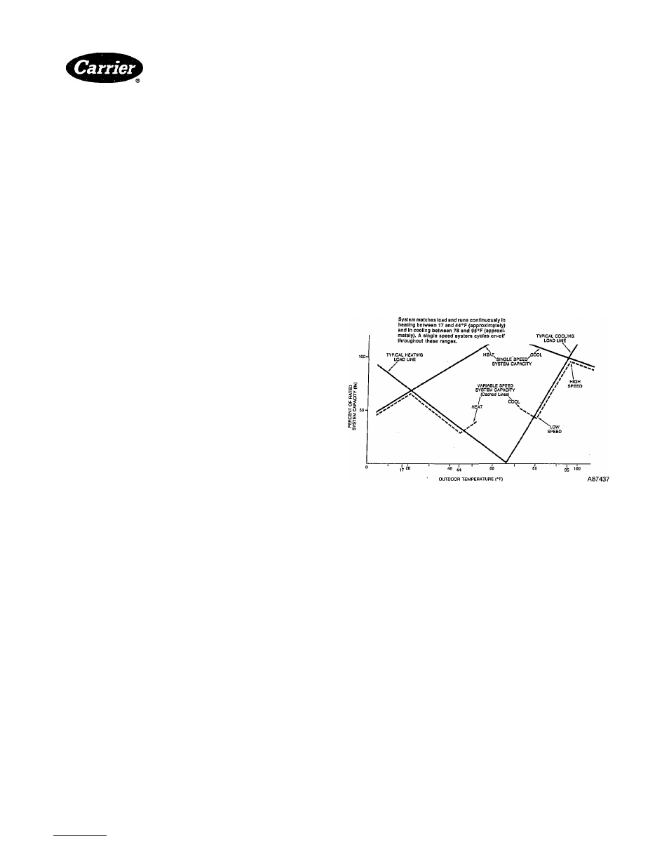
This type of operation results in less on-off cycling (ref. Fig.
1), quieter operation and improved temperature control at
modera:te and low load conditions.
Fig. 1—Variable Speed System Matches Load
STEP 2—Component Functional Description
CONTENTS
Page
38EV, QV Outdoor Units.......................................................... 4
Main Control Board............................................................... 4
Compressor Inverter.............................................................. 4
Compressors................................. .........................................6
Outdoor Coil, Suction Thermistor (Tl, T2).......................... 6
Outdoor Fan Motor/Capacitor.............................................. 6
Outdoor Solenoid Expansion Valve (SEV).......................... 6
High Pressure Switch (HPS).............................. ...................7
Low Pressure Switch (EPS)....................................................7
Emergency Stop Switch (ESS)....................... .......................7
Crankcase Heater and Switch (CH, CHS)...........................7
40QV Fan Coil, 58SSB Furnace Blower Accessory................7
Interface Board ................................................................... 7
Blower Controller................................................................... 7
Blower Motor.......................................................................... 7
Indoor Solenoid Valve (SEV) . ............................................. 7
Indoor Coil Thermistor (T3)..................................................7
Figs. 2 and 3 shows layout of components in the variable
speed control system. This section will describe each compo
nent and discuss its function in attaining proper system
operation.
Manufacturer reserves the right to discontinue, or change at any time, specifications or designs without notice and without incurring obiigations.
Book| 1 I 1 I 4 I 4 PC 101 Cataiog No. 533-895
Printed in U.S.A. FormSSEV, QV-1SM Pg 1
12-87
Replaces: New
Tab I3al5al2al5a