Carrier 38EV024320 User Manual
Page 4
Attention! The text in this document has been recognized automatically. To view the original document, you can use the "Original mode".
38EV, 38QV Outdoor Unît
Main Control Board:
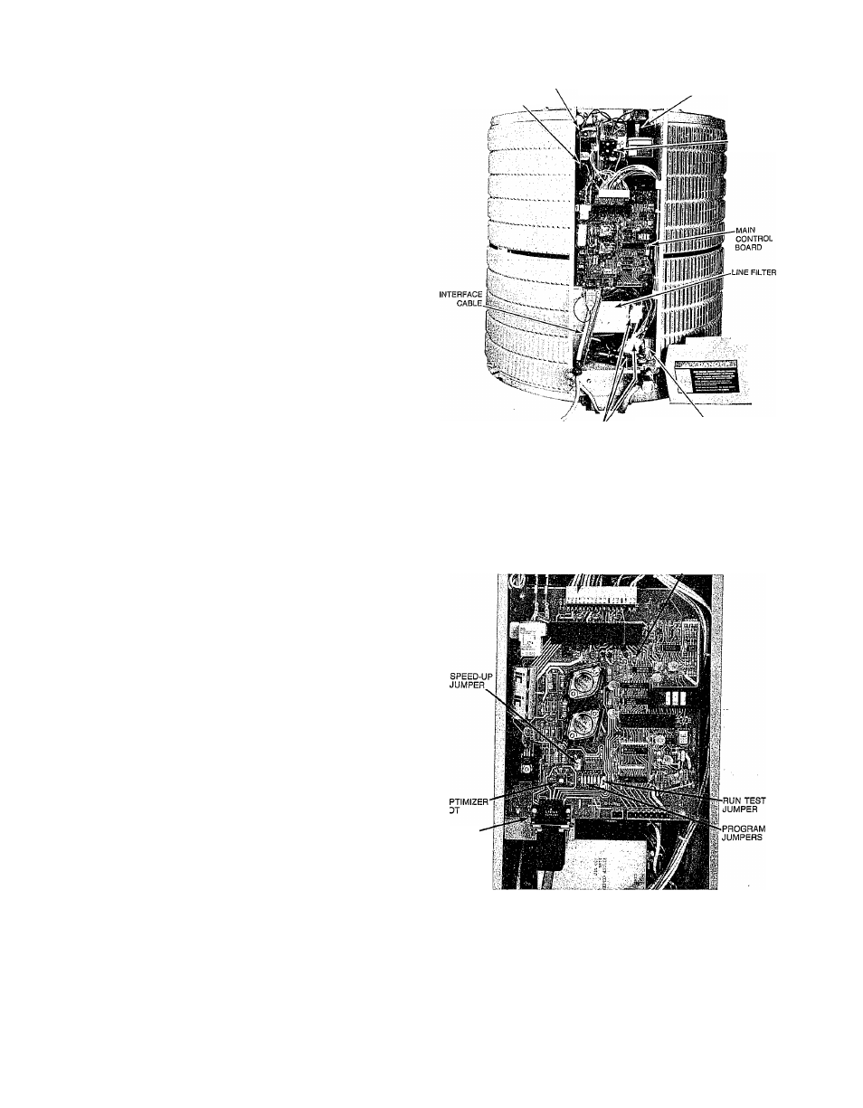
The main control board is located in the front of the 38E V/
QV control box. It is fully visible and serviceable by simply
removing the control box cover, as shovm in Fig. 4. All wir
ing connections for components internal to the unit are at
the top of the board as shown in Fig. 5. Low voltage connec
tions are at thè white 17 pin connector, high voltage (O.D.
fan relay) at the two push on terminals in the upper left. All
connections to the indoor unit aré made through the 15 con
ductor Interface Cable connector located in lower left of the
board.
Thè main "control boárd receives information on system sta
tus from 5 devices (including WT-II thermostat) and uses
it to determine proper control for its 10 outputs. These I/O’s
are listed below: •
Inputs:
1) Thermistor (T2), Suction Line.
2) Thermistor (Tl), O.D. coil (between expansion device
and coil).
3) Thermistor (T3), I.D. coil (between expansion device
and coil).
4) Compressor Inverter (over-current alarm).
5) Thermostat (cool/heat, capacity demand, etc.)
Outputs:
1) Inverter (compressor) speed signal.
2) I.D. Blower Speed Signal (via interface board).
3) O.D. Solenoid Expansion Valve* (refrig, expansion con
trol, heat mode).
4) I.D. Solenoid Expansion Valve (refrig, expansion con
trol, cool model).
5) Main Contactor (inverter/compressor on-off control).
6) O.D. Fan (on-ofif control).
7) Reversing Valve* (on-off control).
8) Aux. Heat (electric or furnace heat on-ofif).
9) On-Board LED (on-off for diagnostics codes, etc.)
10) Thermostat (display of diagnostics codes, etc.)
*38QV Heat Pump Units Only
Compressor Inverter:
NOTE:
The following text describes disassembly of the con
trol box for purposes of explaining inverter, coniponent func
tion only. Inverter components are not serviceable, and
shoüld not be removed from the control box.
Serviceable items include only the main control board, con
tactor and fan capacitor.
Failure of any other component requires replacement of the
entire control box. See instructions included with replace
ment control box for this procedure.
The inverter is made up of 6 components, all mounted in the
38EV/QV control box.
, ~
With the main system control board and backpanel
removed (3-screws) the inverter board is clearly visible (See
Fig. 6). _
w,, /;
Removal of the inverter board allows a view of the rest of
the inverter components, which are pointed out in Fig. 7.
(Refer to Fig. 8) The inverter operates with 208-230VAC,
single-phase input power provided to the Diode Module (or
diode bridge). Here the AG power is converted to high volt
age DC (325V approx.).
The large (black) Smoothing Capacitor in upper right of the
control box is required to Smooth the DC voltage and is at
this 325 VDC potential.
SUB-BOARD
it2
SUB-BOARD
tn
SMOOTHING CAPACITOR
CONTACTOR
CONTROL BOX-TO-UNIT
CONNECTORS
FAN CAPACITOR
A87438
Fig. 4—Control Box, Cover Off
17 PIN
DIAGNOSTIC
CONNECTOR
LED
INTERFACE
CABLE
CONNECTOR &
RETAINER
LATCH
Fig. 5—Control Board
A87216
The DC power is then provided to the Power Modules (3) or
Power Transistors via a buss mounted across all 3 modules.
The power modules drive the 3-phase compressor when the
Inverter Board receives a signal from the main control
board requesting a certain compressor speed. The inverter
board switches each power module on-ofif into a signal simu
lating a single-phase signal. (See Fig. 9A). Each power mod
ule is switched in the same pattern, but 120-deg. out-of
phase from the other two modules, so the total output is in
3-phase form. (See Fig. 9C).