A warning – Carrier 38EV024320 User Manual
Page 10
Attention! The text in this document has been recognized automatically. To view the original document, you can use the "Original mode".
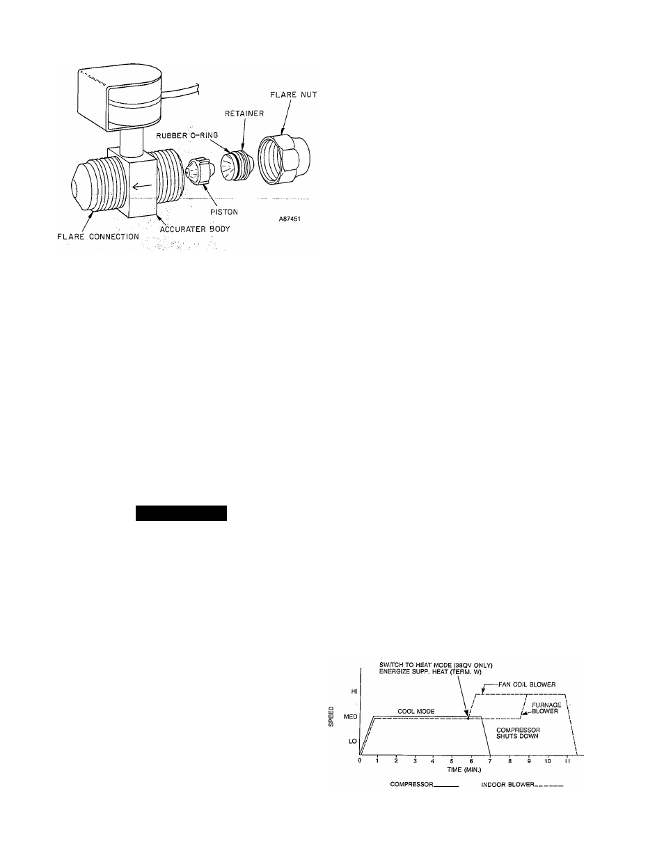
Fig. 17—38QV SEV Parts
The second method involves setting the thermostat setpoint
for a high demand (4-deg.F or more from room temperature)
in the heat or cool mode. To accomplish this, refer to ther
mostat setup instructions, Step 4. This will allow the sys
tem to start and operate normally.
A “Speed-Up” function is available to aid in operational
checkout if the normal startup method is used. The “Speed-
Up” function shortens the delays and timing sequences of
the normal startup routine, and is described in this section.
The system Self-Diagnostic feature (Eef. Troubleshooting,
Step 5) is incorporated in both the Run Test and normal
startup operation.
Run Test-
Initiation—Remove the outdoor unit control box cover, then
apply power to indoor and outdoor units.
A WARNING
High Voltage power is supplied to control box compo
nents immediately upon closure of external main dis
connect. The main contactor is bypassed fqr initi^
charge-up of inverter capacitor (ref. Fig, 8). Electrical
shock or death may result,,
,,
The Red LED on Main Control Board will illuminate for
approximately 30 seconds, and then extinguish.
To initiate “Run Test” function, remove yellow jumper
(board is labeled “Run Test” as ishowri in Fig. 5). Unit will
start soon after jumper is reinstalled in its proper position
on the board.
_
v
Operating Sequence;
In the absence of any diagnosed problems, the system will
operate in the Cool Mode for 7 minutes. It will then switch
to Heat with auxiliary heat on (gas or electric) and immedi
ately ramp the compressor down and off. Auxiliary heat
remains energized for about 3 minutes. See Fig. 18 for a pic
torial of Run Test sequence.
Influence of Diagnostics:
If a problem is diagnosed by the main control board, the
Red LED will flash an error code. Refer to Section 5, “Trou
bleshooting” for interpretation of the flashing code.
The system may, however, react in different ways, depend
ing upon the problem diagnosed. Certain errors wiU cause
one of the following responses:
a) The unit may not start (Error Codes 3-5,8).
b) The unit may shut down prematurely (Error Codes 9,
10). Compressor and/or indoor fan speed may fluctuate
before shutdown as the system attempts to verify or
clear the problem (Error Codes 11, 14).
c) The unit may complete the Run Test properly, but
flash an Error Code during operation. Some diagnos
tics, such as low cheu-ge indication (Error Code 15), are
designed to warn the serviceman of potential problems
but may not affect system operation.
Manual Checkout During Run Test:
Although the system is equipped with self-diagnostic capa
bilities, it should stül be visually and audibly inspected for
proper installation and operation during the Run Test.
A check list of system operational functions is included
below. Refer to Fig. 18 for the sequence of these functions
and check each item. To complete the list, the Run Test can
be initiated more than once.
a) Verify that compressor and outdoor fan operate with
out excessive vibration of the outdoor unit in its
mounted position.
b) Verify indoor blower operates in both the Cool and
Heat Mode.
c) Verify indoor solenoid expansion valve operates prop
erly by listening closely for valve clicking off-on at
about 3-second intervals.
d) Reversing valve switches off (detected by “woosh”
sound) when unit changes to Heat Mode. This sound
also ensures valve was properly energized for cooling
operation (38QV only).
/
e) Verify that indoor blower speed override for gas or elec
tric heat operates properly (blower jumps from medium
to high speed). This function is necessary to guarantee
full blower speed operation when electric heat or fur
nace is on. (Blower control is different for gas vs. elec
tric heat as shown in Fig. 18).
f) Verify that electric heaters or furnace burners operate.
Once the “Run Test” has completed and the unit, including
auxiliary heat is off, the main control board LED will illumi
nate. When it extinguishes, system can be started normally
by adjusting thermostat.
A87452
Fig. 18—Run Test Sequence