A caution, Caution – Carrier 38EV024320 User Manual
Page 7
Attention! The text in this document has been recognized automatically. To view the original document, you can use the "Original mode".
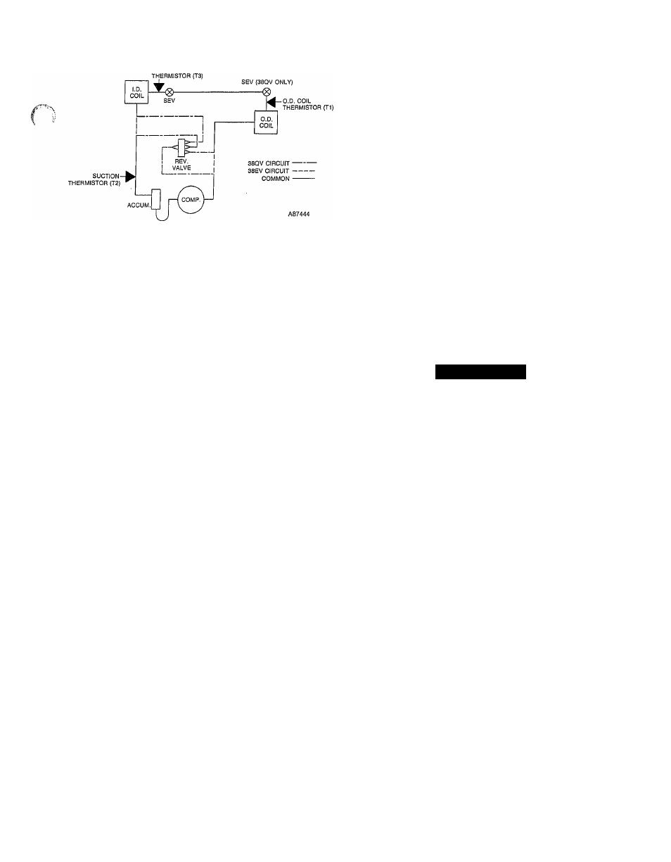
Fig. 10—Thermistor Locations
58SSB Furnace Blower Accessory—Includes the same
motor as the 40QV fan coil. Its controller and interface
board are 115 VAC versions of the fan coil components,
mounted as shown in Fig. 13.
Interface Board—serves three major functions in the
system.
Whenever gas or electric heat is energized, the interface
board takes over control of the blower from the outdoor
unit. It then forces the blower to high heating speed, which
is adjusted at the blower speed trimpot (ref. Fig. 14).
The board also contains the VVTTI thermostat power
supply.
Last of all, it acts as a connection point for input power, and
the control circuit between outdoor unit and indoor compo
nents (i.e., indoor SEV, thermistor, transformer, and blower
motor).
Blower Controller—serves a function similar to the outdoor
unit compressor inverter. It converts single-phase, 60 Hz.
power into a variable frequency output to control blower
motor speed. High and low motor speed settings are adjust
able at a 10-pin connector on the controller.
Blower Motor—is of unique design, containing a permanent
magnet rotor for superior eflBciency.
(
High Pressure Switch (HPS)—is provided for high pressure
protection of the system. It is located on the hquid line in
38EV units, and the discharge hne in 38QV units, (ref. Figs.
2 and 3). Its setting is 425 (+ -10) psig.
Low Pressure Switch (LPS)—is included to provide loss-of-
charge protection.
In 38QV heat pumps the LPS is located in the hquid line
between the outdoor coil and outdoor SEV (ref. Fig. 3). Its
setting is 5 + (+ -3) psig and provides protection in the heat
ing mode.
In 38EV coohng units, the LPS is located in the suction line
between suction service valve and accumulator (ref. Fig. 2).
Its setting is 27 (4--5) psig.
Emergency Stop Switch /EiSSj—Is used only on 38ÉV036
and 38QV036 model units. It is mounted to the top of the
scroU compressor to provide over-temperature protection,
as the scroll has no internal overload. It is located in the
safety electrical circuit in series with LPS and HPS
switches. The ESS is set to open on temperature rise at
265 + -10 deg.F and reclose at 210 + -20 deg.F.
Crankcase Heater and Switch (CH,CHS)—is connected
across the input side of the line filter and operates continu
ously except above the setting of the crankcase heater
switch (70-deg.F) which is located on the liquid hne.
The purpose of the heater is to keep the crankcase warm
during the off cycle and thus prevent dilution of the oil with
refrigerant. This assures good lubrication and prevents loss
of oil from the crankcase during startup. To energize crank
case heater, turn the indoor thermostat to OFF position and
energize electrical disconnect to the outdoor unit. If the elec
trical disconnect switch to the outside unit has been off for
an extended period of time, the crankcase heater should
be always energized for 24 hours before starting the
compressor.
INDOOR UNIT COMPONENT DESCRIPTION
40QV Fan Coils—Are essentially standard Carrier indoor
units with motor replaced by the variable speed motor and
208-230 VAC controller and interface board (ref. Figs. 11
and 12.)
A
CAUTION
An extremely hard or sharp blow to the casing or drop
ping the motor may affect motor operation due to mag
net damage.
Indoor SEV Assembly—Is provided with the 38EV or 38QV
outdoor unit. It must be mounted to indoor unit liquid con
nection during installation. The 38EV SEV assembly pro
vides two expansion orifices in parallel; a main orifice, which
is controlled by the solenoid, and a b
3q)ass orifice (See
Fig. 15).
The b
5qiass orifice is sized to meter refrigerant properly at
low compressor speeds with valve de-energized. At high
Compressor speed, the solenoid is energized, allowing paral
lel flow through a second, main orifice, sized properly for the
additional refrigerant flow needed. At intermediate com
pressor speeds, the solenoid is cycled on-off to control mid
range flow rates.
The 38QV heat pump valve functions in much the same
manner, except the fixed bypass orifice is replaced by a
standard accurator piston. This allows the capability for
non-expanded flow in the reverse direction needed in heat
pumps. This valve, with cutaway, is shown in Figs. 16
and 17. See Table 3 for piston sizes.
The SEV solenoids are energized by a 24 VDC coil, driven
directly by the main control board.
Indoor Coil Thermistor (T3)—Mounted to the SEV assem
bly, it is identical to the outdoor unit thermistors.
STEP 3—Sequence Of Operation
Startup—Once the system is properly installed or serviced,
there are two methods available to start the system and
check operation.
The first method is the “Run Test” function, which is
highly recommended for operational checkout after initial
installation or servicing. The Run Test automatically oper
ates the system in both the heat (including aux. heat) and
cool modes, thus eliminating the need to adjust the thermo
stat a number of times to force system into the desired oper
ating conditions. “Run test” operation is detailed below.