Carrier 38EV024320 User Manual
Page 6
Attention! The text in this document has been recognized automatically. To view the original document, you can use the "Original mode".
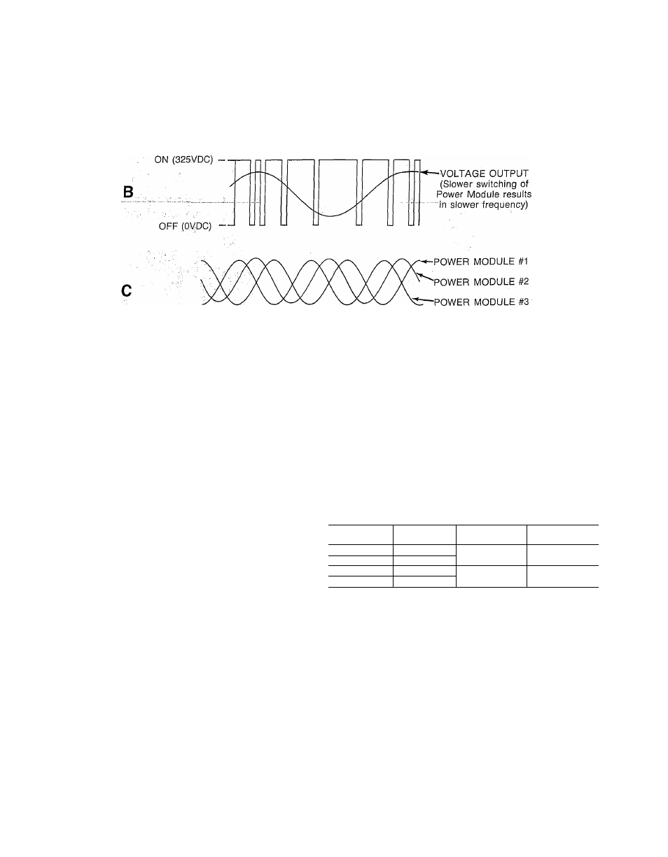
ON (325VDC) —
OFF (OVDC) —
/
\
VOLTAGE OUTPUT
(Average of ON-OFF
■ voltage)
o
A87443
Fig. 9—Inverter Power Module Switching
A change in the speed signal from the main control board
causes thé inverter board to switch the power modules at a
different rate, thus changing the 3-phase output frequency,
and compressor speed. (Ref. Fig..9B),
In summary, the inverter takes a 230V, single-phase, 60 Hz.
frequency input and converts it'to high voltage DC. It then
converts it to 3-phase AC power at frequencies of 30-90 Hz.
to drive the 3-phase compressor at speeds of 1800 to 5400
RPM.
Although other inverter components (shown in Fig. 4) were
not needed in the above'functional description, they are still
necessary to maintain inverter integrity and reliability.
Sub-board #1 is used to suppress electrical noise caused by
power module switching to prevent interference with the
inverter microprocessor. It also contains 2'current loops so
the inverter can monitor its own current output. Sub-board
#2 is an under-voltage protector for the inverter bbardr
Compressors—are of a spedial design to operate reliably
over the 180Ф-540Ф RPM (30-90 Hz. frequency) speed range.
They are driven by a standard design 3-phase motor. ,
—38EV024, 38Qy024 Models—have a reciprocating 'com
pressor with internal PTC heater and internal overload
feature. It has specially hardened valves for high speed
operation, and special oil pump to retedn proper lubrica
tion at low speeds.
Its internal current and temperature sensitive overload
resets automaticaUy when internal compressor motor
temperature drops to a safe level (overloads may require
. .. up to 30 minutes to reset). When an internal overload is
suspected of being open, check by using an ohm-meter
or continuity tester. - -
..:... ■
The internal high Pressure Relief Valve opens at a pres
sure differential of approximately 450-f-50 psig
between suction (low side) and discharge (high side) to
. allow pressure equalization..
See Table 1 for proper oil charge.
—38EV036, 38QV036 Models—have a scroll compressor.
This type of compressor contains no valves, similar to a
rotary type. The “movable” vane osciQates in a cam fash-
ion to force refrigerant around from outer edge to the cen
ter discharge, while compressing it.
The scroll compressor contains no internal overload
devices. Instead, an emergency stop switch (ESS) is
mounted to the top of the compressor (see description
below).
It also requires no high' pressure relief valve. At exces
sive pressure the scroll vane is hfted from its seahng
surface, allowing high tolow'side bypass.
Table 1—Refrigerant and Oil Charge
Unit
Model
Charge
R-22(lb)
Oil
Type
Oil Charge (oz)
New/Recharge
38EV024
Calumet RD-15 or
( , : 55/51
38QV024 ;
, 8;5
Sontex2000
38EV036
: 8.1
Sunisco 4GS
41/39
38QV036
9.5
Thermistors:
Three thermistors are utilized by the main control board to
monitor refrigerant temperatures at locations shown in
Figs. 2, 3 and 10. The same model thermistor is used at all
three locations. Each is mounted in a %6” O.D. tube secured
to the refrigerant hne for improved accuracy and protection
of the device, and then heavily insulated (armaflex tube).
O.D. Fan Motor/Capacitor:
The totally enclosed fan motor is of standard 208-230
single-phase design for single-speed operation. Its related
capacitor, located in lower right of the control box, is also of
standard design.
Outdoor Solenoid Expansion Valve (SEV)—38QV Heat
Pumps Only.
This device is identical to that used at the indoor unit,
except for accurator piston size. Refer to Indoor Solenoid
Expansion Valve Description.