Carrier 38EV024320 User Manual
Page 12
Attention! The text in this document has been recognized automatically. To view the original document, you can use the "Original mode".
sor speed, the solenoid is energized on continuously, allow
ing the extra refrigerant flow required through a second ori-
flce in parallel to the bypass orifice. At intermediate com
pressor speeds, the SEV is cycled on-off at different rates,
depending upon compressor speed. This rate is based on a
5-secpnd on-off period, with the on-time increasing (with
compressor speed) from zero (at low speed) to the full five
seconds on (i.e., continuous on) at high speed. For instance,
at lower speeds, the SEV is on 1 second, off 4 seconds; at
medium speed, on 2.5 seconds, off 2.5 seconds, and so on.
Proper vsllve operation can be checked by listening closely
for the “clicking’’ at the indoor SEV during intermediate
speed operation.
- --—
-----
The system will cycle on-off at low speeds at moderate^ (75-
deg.F) outdoor temperatures. It will operate continuously at
increasingly higher speeds as outdoor temperatures
increase.
Heating Operation—
38QV Systems Heat Pump
Heat pump operation is executed in the same manner as in
the coohng mode. Indoor blower speed and SEV control
“track” or follow compressor speed directly. However, in
the heat mode, only the outdoor unit SEV is operated. It is
cycled in the same pattern as cool mode control, except
cycling on-time is shortened at colder ambients, (i.e. At low
ambients, the SEV may also be cycling on-off rather than
remaining full on when the unit is at high speed).
The system will cycle on-off at low speeds during normal
operation at moderate (50-deg.F) outdoor temperatures. It
will operate continuously at increasingly higher speeds as
outdoor temperatures drop.
When outdoor temperatures drop to a point where supple
mentary heat is required, dr the optimizer function is ena
bled, electric or gas heat is initiated. Electric heat and
furnace operation are described in the following sections.
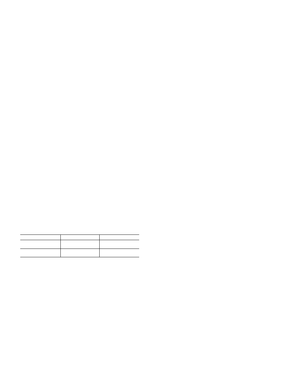
Table 3—38QV Piston Sizes
UNIT
LOCATION
■ PISTON#
38QV024
Outdoor
42
,
- - •
Indoor
49
38QV036 ,
. . '„ Outdoor ,,
. 52
. Indoor...............
63
Electric Heat Control—
(38EV and 38QV ¡Systems)
Electric heat is initiated and controlled by energizing “W”
in the same manner as in standard systems. However, since
the variable speed blower heeds a speed input signal to oper
ate, blower control is considerably different.
Blower Control—In.=a standard 'heat package, energising
‘‘W)’’ energizes the heater sequencer(s). When this is done,
the ian relay is b
3^assed-by 230V power to drive the blower
directly. Therefore, if the fan relay is faulty, the blower still
operates for safe electric heat operation.
40QV Fan Coil Units operate in a similar manner (Ref. Wir
ing Diagrams). However, instead of operating the blower
directly, this ■'230VAC power is apphed to the interface
board at terminals C and 1 (see Figs. 14 and 19). When these
terhiinals are energized by the electric heat sequencer, the
interface board relay breaks the speed signal connection
from the outdoor unit and allows the interface board to
drive the board at a speed set by the adjustable pot on the
board. ; '
When the electric heat (“W”) is cycled off, normal sequencer
operation retains blower control from the interface board
until the heaters cool down. When terminals C and 1 are de
energized by heater package, blower control reverts back to
the outdoor main control board.
Supplemental (2nd Stage) Heat—
(38QV Heat Pump/40QV
Fan Coil Systems Only)
Supplemental heat is required when the outdoor tempera
ture drops too low for the heat pump to handle the load
alone. At this point, the system begins cycling electric heat,
in addition to continuing full speed heat pump operation.
This is done by energizing heater package terminal “W.”
The heaters and blowers are controlled as described above.
A change in blower speed when the interface board takes
over control may not be noticeable, since the outdoor unit is
already operating it at high speed.
It may be noticeable if the blower heating speed trimpot is
adjusted below its maximum setting.
Heating Operation—
(38EV Cooling Systems)
and
Emergency Heat—
(38QV Heat Pump Systems)
Electric or gas heat is operated directly on thermostat
demand on 38EV systems or whenever the 38QV outdoor
unit operation is locked out due to a diagnostic problem.
The blower is controlled by the interface board as described
above. However, since the blower is not being operated by
the outdoor unit during electric heat off cycles, the blower
will cycle fuU-on-off similar to standard systems.
NOTE:
Malfunction of certain electronic control compo
nents can cause lack of Automatic Emergency Heat initia
tion. See Service & Maintenance section for corrective
servicing procedures.
The 58SSB furnace will operate as described in the litera
ture provided with it. The only difference is control of the
variable speed blower. The standard 58SSB furnace
bypasses its fan relay to lock-in blower operation when the
burner is on, just like an electric heat package.
The variable speed blower package switches blower control
to its interface board when “W” is energized, in the same
manner as described above for “Electric Heat Control.”
(The furnace interface board design is identical to that for
the 40QV fan coil, except it is a il5VAC yersioh)/
The blower will remain off for 2r3 minutes while the burner
ignites and warms the heat exchanger. The blower wUl then
start, and ramp to low speed for a short period before going
to full speed. 'When “W” is de-energized, the blower will
stay on for a short period to use the remaining heat from
theexchanger.
Supplemental (2nd Stage) and Optimizer Control—
(38QV
Heat Pump/58SSB Furnace Systems)
Unlike fan coil operation, the furnace wiU not operate simul
taneously with the heat pump. Therefore, whenever the out
door temperature drops to where the heat pump cem no
longer match the load, or the optimizer setpoint is reached,
the heat pump wfll shut down when. furnace startup is
requested (“W” is energized). At this point, the heat pump
wfll also shut down the indoor blower (except if ,the thermo
stat is in the fan-on position). The normal furnace delay of
2-3 minutes wfll then pass before the blower is cycled back
on, to allow the heat exchanger to heat up. Once the thermo
stat is satisfied by the furnace, it will cycle off. Operation
wfll alternate between furnace and heat pump, until either
the heat pump can handle the entire load, or the optimizer
setpoint is reached. If the optimizer setpoint is reached, the
heat pump wfll be locked out (a minimum of two hours) and
the furnace will cycle directly on thermostat demand.
I