Fig. 20-vvt-ll mst thermostat – Carrier 38EV024320 User Manual
Page 13
Attention! The text in this document has been recognized automatically. To view the original document, you can use the "Original mode".
•r
■■
Adaptive Defrost—
38QV Heat Pump Systems utilize an adaptive defrost con
trol which clears the coil of frost only when necessary.
Based on coil conditions and outdoor temperature, the time
between defrosts is adjusted between 30 minutes and four
hours, as described below.
Between Defrost Period Calculation-
Defrost monitoring is begun when the O.D. coil thermistor
temperature drops below 32 degrees F. The first defrost will
occur 45 minutes later.
When the unit is ready to defrost, the pre-defrost O.D. coil
thermistor temperature (frosted coU) is memorized, and thè
unit then switches to defrost. A short time after defrost is
completed, a post-defrost thermistor temperature (clear coU)
is memorized.
The after-defrost (clear cod) temperature is used to estimate
outdoor temperature and the optimum pre-to-post defrost
coil temperature change (i.e. frosted coil vs. clear coU
temperature).
The time period to the next defrost is then determined by:
a) If defrost time was less than 5 minutes, add 30 minutes
to previous period.
b) If defrost time was maximum (10 minutes), and O.D.
con temperature at termination was:
—more than 45 degrees F, divide previous period in
half.
—less than 45 degrees F, next period will be 30 min
utes.
c) If defrost time was greater than five and less than 10
minutes, the new time is calculated by:
.
. ,
optimum temperature change
*
previous peno x actual post-defr. temp..minus pre-defrost temp.
*The new period calculated by this method cannot be less
than half, or more than double the previous period.
Other Limitations:
Maximum period between defrosts is 4 hours.
Minimum period between defrosts is 30 minutes, except:
The initial defirost after coming out of optimizer mode will
occur 15 minutes after startup.
Defrost Sequence—
When a defrost is initiated, compressor speed is dropped to
medium speed. This is done to mininiize shock to the com
pressor. The reversing valve and heat (terminal “W”) relays
are energized, the outdoor fan relay de-energized, and com
pressor then ramped to full speed for a rapid defrost.
Defrost is terminated on any of the following occurrences:
a) O.D. coil thermistor rises to 80 degrees F (when out
door temperature is above 10 degrees F).
b) O.D. coil thermistor rises to 60 degrees F (when out
door temperature is below 10 degrees F).
c) 10-Miuute maximum defrost period.
The system then ramps down to medium speed, returns to
heat mode, and returns to the pre-defrost speed.
Heat/Cool/Auto Control-
This thermostat function controls as in standard systems.
Heat or cool operation may be requested separately. The
“Auto” position allows the' system to switch between these
two modes automatically as required to satisfy thermostat
setpoint demand.
Fan-On/Auto-
With the fan-auto mode selected, the indoor blower will
-------------------------------------- /
---------------
It
—1
^OWER
HEAT
SETPOINT
1
lO 'O oii—
•HP’OBQV)
•AC’(38EV).
\ /
\ /
\ /
COOL
\
4 ’HP' or 'AC:.
V
/
■HP
65
HP
•66
HP
00
56
;;
56
-HEAT
05
z'
\
N
' \
SETPOINT
N
NORMAL POWER-UP
IMPROPER
CONFIGURATION
SYSTEM
DIAGNOSTIC
ERROR CODE
ON
I
OFF
I
68
69
70
71
72
76
77
78
79
ROOM TEMPERATURE
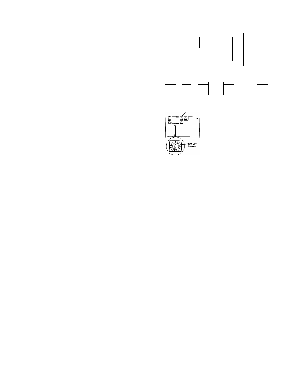
Fig. 20-VVT-ll MST Thermostat
A87454
cycle on-ofil with the outdoor unit and/or the electric/gas
indoor unit.
The fan-on mode will keep the indoor blower operating at all
times. The blower will operate at low speed during system-
off intervals.
STEP 4 VVT-II Thermostat Startup/Troubleshooting
The MST-04 or MST-16 thermostat consists of a printed cir
cuit board, a connector board, and a wall mounted case.
A thermostat software revision of 6.7 or higher is required.
AU wiring connections to the thermostat are made to the
connector board.
.
Mount the thermostat as described in 38EV or 38QV out
door unit installation instructions, or follow the Installation
Instructions included with each control. Thermostat must
be wired as shown in Figs.. 36 and 37.
Fig. 20 shows front view of the VVT-II MST thermostat.
Start-Up Procedure:
Close indoor main disconnect.
Normal Display—The thermostat will. display HPOO (for
38QV systems), ACOO (for 38EV systems), or 4 zeros, then
switch to the normal heating/cooiing setpoint as shown.
Blinking Display—If the thermostat display blinks on .and
off or is erratic, it is an indication that a wiring connection
is not correct, or that the thermostat is not receiving ade
quate power. Check the wiring connections and the supply
voltage (22VAC rninimum) at terminals SEC-1 and SEC-2
on the interface board. Make certain the thermostat ribbon
cable has been inserted into the connector board correctly.
Display Four Zeros—If the display shows four zeros upon
power-up, and then displays “HF-11,” it indicates that the
thermostat is currently configured for a multiple-zone sys
tem. It must be reset for single-zone control.
Setting Thermostat For Single-Zone Control—
To correct the configuration, set the rotary switch to posi
tion #1 (ref. Fig. 20). A number and “ON” or “OFF” will