A warning – Carrier 38EV024320 User Manual
Page 11
Attention! The text in this document has been recognized automatically. To view the original document, you can use the "Original mode".
A WARNING
Unit is capable of restarting on normal thermostat
demand soon after Run Test is completed. Personal
injury can result.
(J
Normal System Startup Sequence
Apply power to indoor units via main disconnect switches.
If outdoor unit control box cover is removed, main control
board LED wiU light and extinguish after 30 seconds.
Thermostat will display HPOO (for 38QV units) or ACOO (for
38EV units).
Set up thermostat in heat, cool or automatic mode for room
temperature desired (Ref. Thermostat Operation, Trouble
shooting Section 4).
Thermostat setpoint must be 2-deg.F or more away from
room temperature for the system to initiate a startup.
(Room temperature can be displayed on thermostat by
pressing both heat setpoint adjustment buttons to right of
display simultaneously).
Startup Sequence
NOTE:
Startup delays and sequence times can be shortened
for system checkout by initiating “Speed-Up” jumper,
described below.
a) Time Guard-
Normal Ambient Startup—Mter applying power and/
or adjusting thermostat setpoint, the system will
undergo a 5-minute delay before starting. This will also
occur any time the system cycles off normally, to pre
vent unnecessary on-off cycling.
Low Ambient, Initial Startup—When outdoor tempera
tures are near or below 20-deg.F, the system will
undergo a
26-minute delay bn initial power-up only.
This allows the crankcase heater to at least partially
warm up compressor before startup.
Siartop—Compressor wffl start and ramp up to low
speed, outdoor fan wffl come on. Indoor blower will
start in a similar manner to compressor, 30 seconds
later.
b)
Low Speed
L
oc
A-I
ti
—
After starting, the' unit will lock
in at low speed for a period of 8 minutes. This is done
for the following reasons:
1. System self-diagnostics wffl monitor system condi-
tionis during this period to verify proper system
operation.
2. Allows indoor blower time to circulate and slowly
mix possibly cold ductwork air with room air, thus
avoiding erratic speed fluctuations due to unstable
thermostat readings.
c) Transition to Normal Control—li the thermostat is sat
isfied during the Srminute period at low speed, the sys
tem wffl remain at low speed for 4 more minutes and
then shut down. If not, it wffl speed up depending upon
thermostat demand. The startup sequence is complete.
“Speed-Up” Function
The “Speed-Up" jumper is a yellow jumper, similar to the
“Run Test” jumper. It’s located on the outdoor unit main
control board next to the label “Speed-Up” (ref. Fig. 5). The
function is initiated by removing and reinstalling the
jumper during the sequence period you want to eliminate.
For instance, if you want to ehminate the time guard period
before startup, wait for the LED to extinguish after power-
up. Then pull and reinstall the “Speed-Up” jumper. This
wffl shorten the respective period, (i.e., 5 minutes down to 2
minutes for the normal time guard, or 20 minutes down to 4
minutes for low ambient initial startup).
If the jumper is pulled and reinstalled during a sequence
period listed in Table 2, it wffl shorten that period as indi
cated. The speed-up function will then cancel automatically
when the next event listed in the table occurs. To shorten
subsequent sequence periods, the jumper must be initiated
again.
Table 2—Speed-Up Function
Initiate The
Jumper During
This Period
Period Wiil
Shorten From
Normal- to Speed-Up
Speed-Up Function
Will Cancel
When
—Prestart
Time Guard
5 Min.—2 min.
OR* 20 Min.—4 Min.
Compressor Starts
—Low Speed
Lock in At
Startup
8 Min.—
40-50 Seconds
Compressor Begins
Ramping Above
Low Speed, Or
Shuts Down
— Between Defrost
Periods (Beiow
32-Deg.F
Ambient)
45 Min.—4-5 Min.
(1st Defrost)
30 Min.-4 Mrs.-
3-24 Min.
(Subsequent
Defrosts)
Unit Initiates
A Defrost
—During Defrost
4-10 Min.-
24 Sec-1 Min.
Defrost Termination
*Low Ambient Initial Startup
Cooling Operation
Compressor—
During normal operation, the compressor speed will vary,
based on thermostat demand, from 2200 RPM at low speed
to 5000 RPM at high speed.
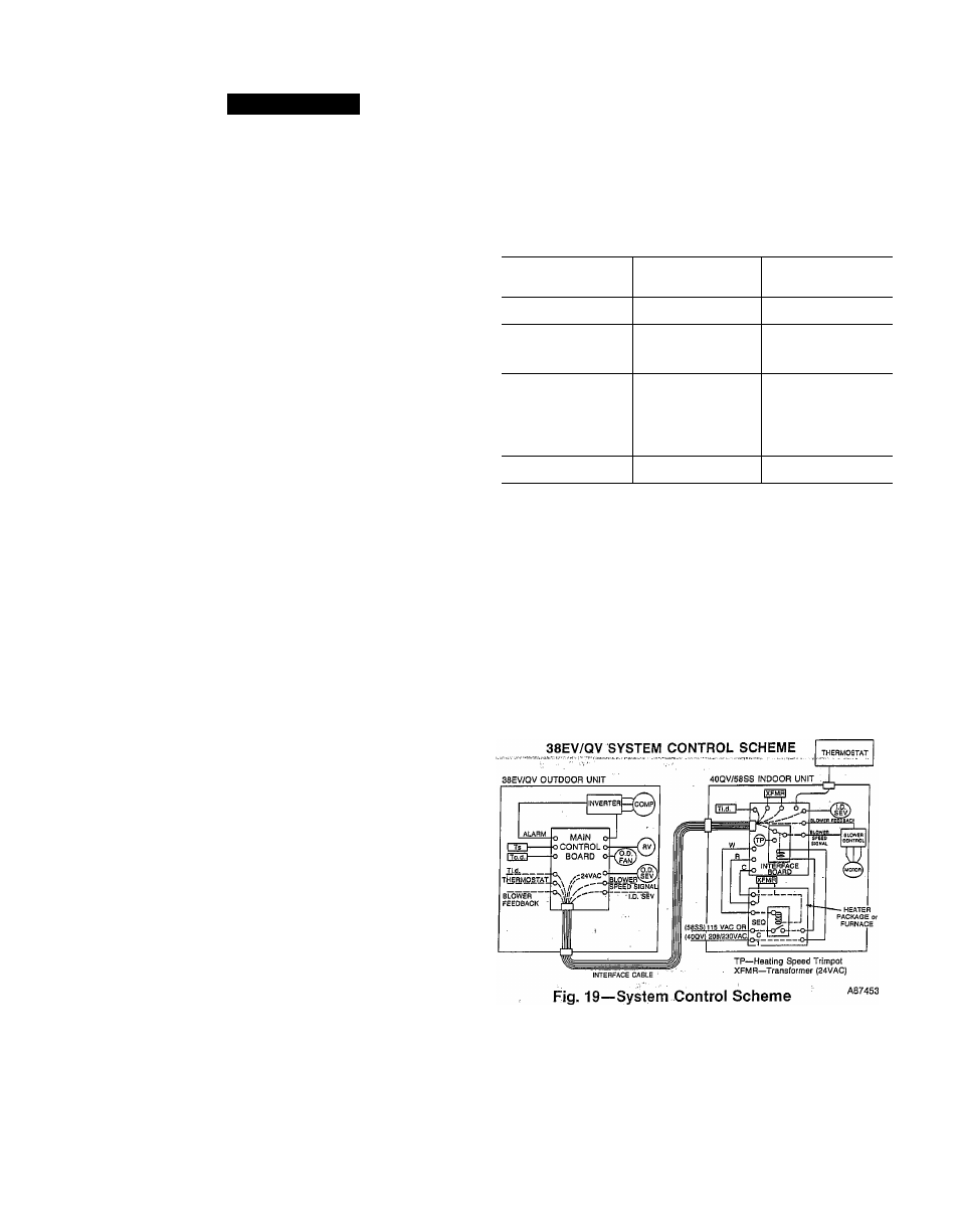
Indoor Blower-
Blower speed (or airflow) wffl “track” or follow compressor
speed; i.e., when the compressor is at low speed, so is the
blower. If the compressor ramps^oTiigh.speed, the blower
ramps to high speed simultaneously. This speed signal is
sent from the outdoor unit main control board, through the
indoor unit interface board to the blower controller. (See
Fig. 19).
Outdoor Fan—
The outdoor fan cycles on-off with the compressor.
Solenoid Expansion Valves (SEV)—
In the cooling mode only, the SEV at the indoor unit is oper
ated. SEV operation “tracks” or follows compressor speed
directly. At low compressor speed operation, the solenoid
remains off and aU refrigerant flow is directed through a
bypass orifice in the valve body (38EV systems). In 38QV
systems, the bypass orifice is located in the accurator piston
(Ref. Component Description, Section 3). At high compres-