A warning, A caution – Carrier 38EV024320 User Manual
Page 15
Attention! The text in this document has been recognized automatically. To view the original document, you can use the "Original mode".
Error Code 11—Reversing Valve Failure................... 26-27
Error Code 14—Indoor Coil Freeze................................ 28
Error Code 15—Low Refrigerant Charge..................29-31
System Malfunctions with No Error Code
No LED on power-up.....................................................32-33
No Indoor Blower Operation........................................34-35
Electric/Gas Heat Failure..............................................36-37
Miscellaneous Malfunctions.............................................. 39
BEFORE TROUBLESHOOTING THE SYSTEM
This troubleshooting guide covers all components of the
38EV/QV variable speed system, including outdoor and
indoor units.
See previous section for thermostat troubleshooting. (Ther
mostat Error Codes HF and SF).
A WARNING
High voltage (300VDC) circuit remains energized after
main disconnect is opened. Normal capacitive discharge
time is ten (10) minutes, but this period may be
extended indefinitely by component failure. Before
servicing, always check with D.C. voltmeter between
contactor terminal #23 (violet wire) and ground. Always
reinstall safety shield in top of control box after servic
ing. Electrical shock can cause personal injury or death.
Before replacing components to correct a system malfunc
tion, always inspect circuit for damaged or oorroded wiring.
Connectors should be inspected for improper mating. They
should then be unplugged and examined for corrosion, dam
age or incomplete terrhinal insertion. This procedure is espe
cially required when a system malfunction is intermittent
(does not occur consistently).
Clean and/or repair wiring as required. A special accessory
terminal kit (Carrier Service Part No. 38QV660001) includ
ing terminal extraction tools is available through your local,
distributor.
Use high quality multimeter for troubleshooting electronic
devices in this system.
Self-Diagnostic Error Codes—
Error codes are indicated at an LED located on the outdoor
unit main control board (Ref. Fig. 5), and on the indoor ther
mostat display (Ref. Fig. 20).
Control board LED error codes are shown as a series of %
second on, % second off flashes, followed by a 10-second
pause before repeating.
Thermostat display error codes are shown as a two-digit
number, preceded by “HP” on 38QV heat pump systems or
“AC” on 38EV coohng-only systems.
As an example, when an error Code #5 is diagnosed,
“HP05” or “AC05” will be displayed at the thermostat
when 5 flashes are indicated at the control board LED.
Automatic System Restarts on Diagnostic Shutdown—
AU diagnostic shutdowns described in this text wfll cause as
many as five restarts before final shutdown and compressor
lockout. The system wfll remain off for at least five minutes
(time guard function) before attempting each restart.
Note that the control board LED wfll display the error code
after each shutdown. The thermostat display will indicate
an error code only after final compressor lockout.
A CAUTION
Whenever troubleshooting system with power on and
control board LED flashing error code, check ther
mostat display. If error code is not indicated at thermo
stat, automatic restart is pending. Servicing of equip
ment at time of automatic restart may cause personal
injury.
How to “Clear"Error Codes—
Indoor unit power (i.e., controLpower) must be broken and
reset in order to cancel system lockout on a diagnostic.
. The-Self-Diagnostics, feature is designed .to monitor inputs
(thermistors and inverter alarm) and take over control of the
system if these inputs go out of normal range.
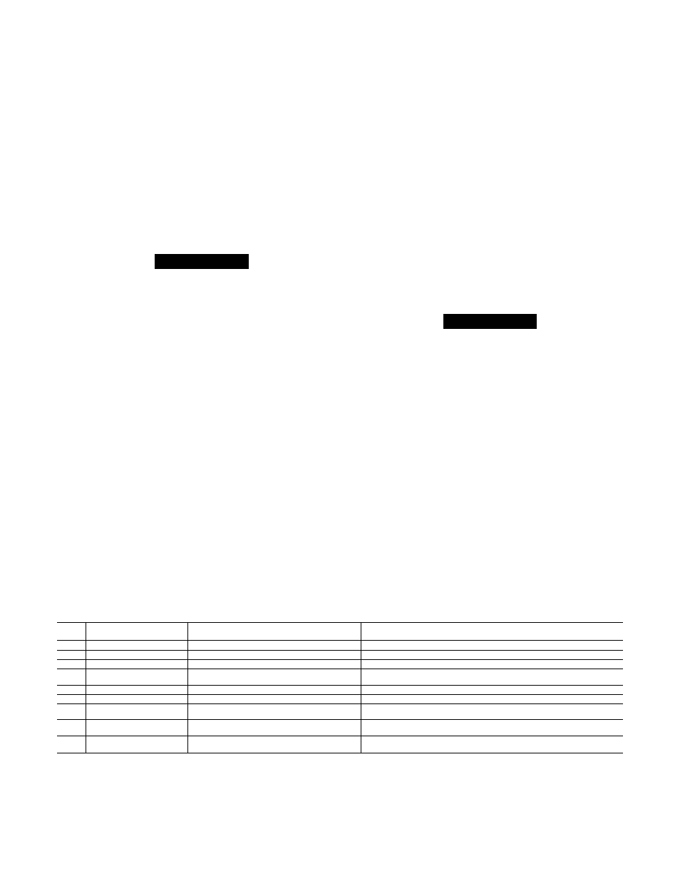
Table 4 lists each of the Self-Diagnostic error codes, the con
ditions, that cause the code, and how the system reacts to
each condition.
Troubleshooting System withRower On—
Always bredk power to both indoor and outdoor units when
servicing, except as indicated in the following procedures.
Table 4—Self Diagnostic Error Codes
ERROR
CODE
DESCRIPTION
CAUSE
^ SYSTEM REACTION
3
O.D. Coil Thermistor Failure
Thermistor reads greaterthan 160'’F or less than -dO^F '
: Immediate Shutdown or no startup*
4
Suction Thermistor Failure
Same as above
Same as above*' - - ■
5
i.D, Coil Thermistor Failure
Same as above
Same as above*
8
Locked Compressor Rotor
Inverter alarm—on within 2 minutes after contactor
energization
Sameasabove* -
9
Overcurrent Trip -
Inverter alarm—on after 2 minutes of run time (See Note 1)
Compressor slows down to cancel alarm. If alarm stays on system shuts down.
10
Contactor Control. Failure
No change in thermistor readings (See Note 2)-
Immediate Shutdown or no startup*
11
Reversing Value Failure
O.D., IrD. Coii Thermistor readings change in wrong
directions (See Note 2).
Compressor speeds up to shift valve. If thermistor readings don't switch direction,
system shuts down.* - - ■
14
indoor Coil Freeze
Suction Thermistor reads less than 32°F in Cool Mode.
Blower speeds up to raise suction temperature above 35°F. If so, blower continues
operation at higher speed. If not, .system shuts down.*'
15
Low Refrigerant Charge
Suction thermistor reads much higher than I.D.
coil (cool), or O.D. coil (heat) thermistor.
No effect on system operation. Error code on control board LED only.
NOTES:
* System attempts 5 restarts (each followed by 5 minute timeguard) before lockout and error code display on thermostat.
1. Inverter alarm comes on at 100% of rated inverter output-current. Control board ramps compressor speed down until alarm goes off at 85% of rated
current. If control board drops compressor speed to minimum and alarm remains on, it knows inverter has tripped, and shuts system down. (Inverter
trip requires reset of inverter power through contactor to shut off alarm).
2. Control board compares thermistor readings after 5 minutes of run time to readings taken at startup (contactor energization).