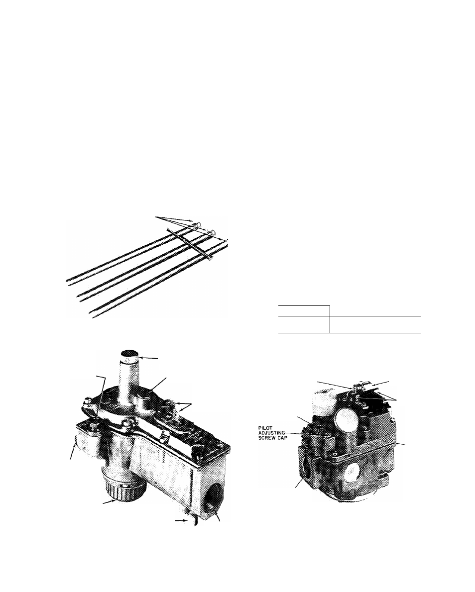
Fig. 8 — unit gas valves – Carrier 48DH User Manual
Page 7
Attention! The text in this document has been recognized automatically. To view the original document, you can use the "Original mode".
Example: measured resistance .32 ohm x 2 - .64
.64 divided by 0.032 = 20
Cut off 20 in. of resistance wire.
CHECK MAIN BURNERS
1. Check automatic pilot as previously described.
2. Measure and adjust main burner gas input as
described in Service section.
3. Turn main gas valve to “On” position and
operate unit for at least 15 minutes with all
access panels in place.
4. Remove heating section access panel.
5. Turn each primary air adjustment screw (Fig. 7)
clockwise until yellow tips appear on burner
flames. Then turn each screw counterclockwise
(about 3/4 turn) until flames become clear,
almost transparent blue with a well defined
inner cone. If the flames lift off the burner
ports, turn the screw clockwise slightly.
BURNER ADJUSTMENT SCREW
FINAL HEATING SYSTEM CHECKOUT - Move
thermostat dial above and below room temperature
setting several times, pausing at least 5 minutes
between cycles. Check pilot flame, main burner
ignition, flame characteristics and indoor (evap
orator) fan motor time delay relay operation.
Replace heating section access panel.
COOLING SYSTEM CHECKOUT
1
.
2
.
3.
Turn power on.
Set room thermostat selector switch at “Cool”
or “Auto.” and dial setting below room
temperature.
Move thermostat dial above and below room
temperature several times, pausing at least 5
minutes between cycles. Check fan and com
pressor operation. If compressor fails to start,
refer to the following section entitled Check
Compressor Start.
Check unit operating voltage. Voltage must be
within ±10% of nameplate voltage.
Check cooling effect at air outlets.
Check that field-supplied filter is in place.
Check action of safety devices and controls.
Check Compressor Start
— Single phase compres
sors of split capacitor (PSC) type require equalized
system pressure to start. When supply voltage is
within ±10% of nameplate voltage and the compres
sor fails to start, give the compressor a temporary
capacitance boost.
Use a start capacitor, sized as listed below, with
a bleed resistor wired across the terminals.
4.
5.
6
.
7.
Fig. 7 — Main Burner Adjustment
UNIT SIZE
CAPACITOR RATING
002 thru 004
045 thru 005
108
135 -
130 mfd, 370 V
155 mfd, 370 V
PILOT GAS LINE
CONNECTION
REGULATOR
ADJUSTING SCREW CAP
REGULATOR VENT
AND DUST CAP
LOW-VOLTAGE
CONNECTIONS
PILOT ADJUSTING 'i?
SCREW CAP
MANUAL SHUTOFF
VALVE AND PILOT COCK
NATURAL GAS VALVE
PIPE PLUG FOR
PRESSURE TAP
VALVE
OUTLET
REGULATOR ADJUSTING
SCREW CAP
MANUAL SHUTOFF
VALVE AND-----------
PILOT COCK
PILOT GAS LINE
CONNECTION
REGULATOR VENT
LOW VOLTAGE
CONNECTIONS
PRESSURE
TAP
(HIDDEN)
MAIN GAS LINE
CONNECTION
LP GAS VALVE
Fig. 8 — Unit Gas Valves