Carrier 48DH User Manual
Page 11
Attention! The text in this document has been recognized automatically. To view the original document, you can use the "Original mode".
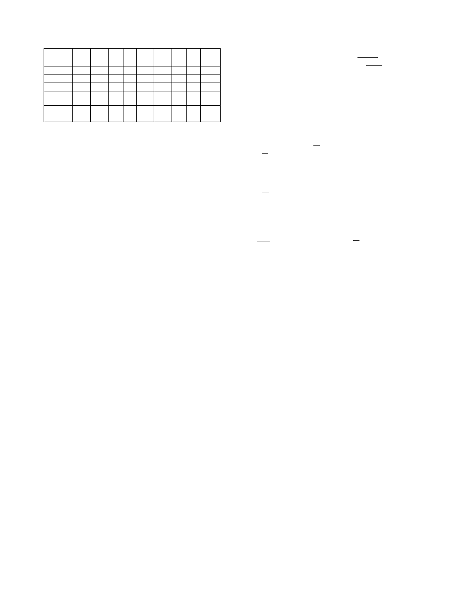
Table 6 — Gas Rate (cfm)
Table 7 — Chargemaster®Charging Chart
UNIT
48DL
002
48DH
002
481
003
3L
'004
48 DM
004
48 DH
004
_48
045
3L
005
48DH
005
Nat 1000
.93
1.33 1.33 1.33 1.83
2.08 1.67 1.83 2,50
Nat 1050
.89
1.27 1.27 1.27 1 .74
1.93 1.59 1.74 2.38
Nat 1100
.85
1 21
1 21 1 21 Ì .66
1 89 1 52 1 66 2.27
Butane
3200
28
41
41
41
.57
65
52
57
78
Propane
2500
.37
.53
53
53
.73
83
67
73 1 00
Charging
— Standard 1/4-in. Schrader service
connections are provided on the high and low sides
of the refrigerant system for charging and
evacuation.
To add complete charge, first evacuate the unit
and then weigh in the full charge stamped on the
unit nameplate. Evacuation procedures can be
found in Carrier Standard Service Techniques
Manual, Chapter 1, Form SM-1. If the previous
charge is blown to atmosphere, weigh in the full
charge less 0.15 lb (2-1/2 oz). For units having a
partial charge, use the Chargemaster® procedure
in the following paragraphs.
CHARGEMASTER OPERATION “ Operate unit
for 10 minutes before using Chargemaster.
1. Tape Chargemaster feeler bulb to unit suction
line. Insulate bulb. Ensure suction line is clean
for good contact with bulb.
2. Connect refrigerant drum to Chargemaster inlet
port with drum in position for vapor charging.
3. Connect Chargemaster outlet port (loosely) to
unit suction line Schrader valve.
4. Crack valves on refrigerant drum and Charge-
master to purge lines from drum to suction line
Schrader valve. After purging lines, close valve
on Chargemaster only. Tighten Chargemaster
connection at suction line Schrader valve.
5. Measure outdoor air dry-bulb temperature.
6.
Read evaporator temperature at red needle
position on Chargemaster temperature gage and
suction line temperature at black needle.
CAUTION; Do not read evaporator temper
ature with Chargemaster valve open.
7. Enter Chargemaster Charging Chart, Table 7, at
outdoor air temperature (step 5) and evapora
tor temperature (step 6). Find the suction line
temperature required for correct system charge.
If actual suction line temperature (step 6) is
higher than table value, the system is under
charged; if lower than table value, the system is
overcharged.
Example (See Table 7): At outdoor air temper
ature of 84 F and evaporator temperature of
40 F, the system will be correctly charged at
66 F (±2 F) suction line temperature.
8. Add charge by slowly opening Chargemaster
valve. If necessary, reduce charge by bleeding at
liquid line Schrader valve. Check outdoor air
and evaporator temperature during procedure.
OUTDOOR
TEMP (F)
60_
62
64
66
70
72
74
76
78
80
Z2
84
J6
88
~
90
92
94
96
98
Too
102
104
106
108
no
112
114
EVAPORATOR TEMP (F)*
2
i
X_25 f J8 I 31 ] I 37T^T43l
Suction Line Temperatures
45
32
30
28
27
40 51
38
37
35
34
32
31
30
_29
27
26
49
47
45^
43
41
'39
37
36
_35
33
32
FsF
29
60
57
54
52
50
48
46
44
42
67
64
6Ì
58
56
54
52
40
50
72
69
66 ;
63 •
75
61
> 7 2
59
38T' 48; t. .57
37
35
34
33
46
i4
42
36
55
53
51
49
47
45
44
42
41
39
68
66
63
61
59
57
46
41
61
59
57
55
53
51
46
78
75
67.
65
63
61
59
53
50
90
86^
'à'3
80
77
75
73
70
68
65
63
61
59
■
. Example
^Saturated evaporator temperature is the equivalent temperature
of pressure taken at unit suction line Schrader valve.
If they change, refer back to Chargemaster
Charging Chart for new values.
Correct use of Chargemaster ensures an opti
mum refrigerant charge will be in system when
conditions and system components are normal.
However, the Chargemaster does not solve or fix
system abnormalities. It indicates correct charge
for condition of system. It will not make correc
tions for dirty filters, slow fans, excessively long or
short suction lines or other abnormal conditions
This charging device ensures that a correct relation
ship exists between outdoor temperature, evap
orator temperature, and suction line temperature,
on a specific system.
-» Part Removal
C.4UTION: System contains oil ajtd refrigerant
under pressure. Do not use torch to remove
component. Wear' yoox protective gog^es,
1. Shut off electncai power to unit.
2. Relieve all pressure from system.
3. Out connecting piping with tubing cutter.
4. Remove component from unit,
5. Unsweat piping stubs carefully. Oil may
tgirite when exposed to torch flame,
^ WELDED HERMETIC COMPRESSOR - Make
certain that all safety codes are followed Use
10