Carrier 48DH User Manual
Combination heating/cooling units
Attention! The text in this document has been recognized automatically. To view the original document, you can use the "Original mode".
Number One
r
AirConditioniiX)
Maker
e
Division of Cairier Corporation
Syracuse New York
Combination Heating/Cooling Units
INTRODUCTION
The 48DH, DL and DM combination heating/
cooling units are complete systems designed for
outdoor installation on slab or rooftop.
Installation consists of: rigging and mounting
the unit; attaching ductwork; making single gas,
electrical and condensate connections; and attach
ing thermostat leads. A field-furnished filter rack is
required in the return air stream.
RECEIVING THE UNIT
Examine the unit carefully for any damage
incurred in shipment. If found, file claim with
transportation company immediately.
Check unit nameplate to ensure that unit
electrical requirements match available power
supply, and that unit is designed for use with the
proper gas type (natural or liquefied petroleum).
Leave unit on shipping skids until ready for
mounting.
INSTALLATION
Check national and local gas and electrical
codes and local building codes for any special
installation requirements.
Unit Location
— Install unit outdoors and as close
to building duct openings as possible. Unit may
face in any direction since neither the condenser
air inlet nor the flue outlet (Fig. 1) are affected by
wind. Do not locate unit near sources of con
taminated air.
Although the unit is weatherproof, position
unit so that water and ice from roofs or eaves
cannot fall directly on the unit.
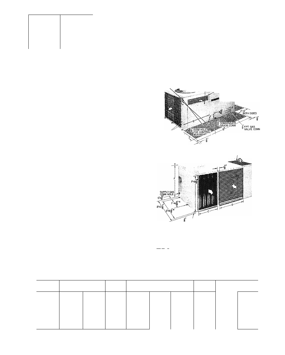
SPACE LIMITATIONS - Provide sufficient space
for unimpeded air flow and for wiring and servicing
unit (Fig. 1).
,
CONO UNIT
2-0 OVERHEAD SPACE SECTION
REQ FOR SERVICE AND ACCESS PANEL
AIR FLOW
;
002
'
o n l y
.
.JSSiiSOc
045 8005
HEATING
SECTION
i ACCESS PANEL
SERVICE ^
OPENINGS
^0'
BOTH
s i d e
:
ACCESS SIDE
FLUE OUTLET
—,
—X::...
n DIAM HOLE
® FOR LINE
POWER WIRING
____WIND CAP ASSEMBLY (CONDENSER AIR OUTLET
îLÎÎÎ
002 UNIT ONLY)
COMBUSTION AIR
• DIAM*
(S
m
TG HOLES)
*This dimension is not applicable to 002 units because there are no
mounting rails
Space required for service Design certified by A G.A. for in-
stallation on combustible type floor with a minimum ciear-
ta-'iiEiEJ ance space of 1 in. on duct connection side, and 12 in on
remaining sides
O'
Indoor (Evaporator) Air
Fig. 1 — Physical Data
Table 1 — Base Unit Dimensions (ft-in.)
) Condenser Air
UNIT
48DL
48 DH
48DL
48DL
48 DM
48 DH
48DL
48DL
48DH
002*
003
004
Q45
005
A
3-10
3-10
4- 7
4- 7
3_2
5- 2
5- 2
5- 2
5- 7
\
В
—
—
4- 7
%
4- 7
%
5-2У
5- 2
%
5- 2
%
5- 2У
5- 8У
C
0
-
1 0
V
3
0 - 1
оу
0
-юу
0 - 1
оу
1-ЗУ
1- 5У
1- ЗУ
1- ЗУ
1 9
D
0-11 Уз
0 - 1 1
у
1- 2
1- 8
1-8
1- 8
1-11
1-11
1-11
E
1- 0
1- 0
1- 0
1- 0
1-0
1- 0
1- 0
1- 0
1
- оу
F
2- 2У
2- 2
%
2- 2У
2- 2У
2-2У
2- 2У
2- 2
%
2- 2
%
2- 2У
G
—
—
2- 2У
2- 2У
2-4У
2- 2Ув
2- 4У
2- 4У
2- 4У
H
0-11У
0-11У
0-11У
0-11У
1-4У
1- 4У
1- 4У
1- 4У
1- 4У
J
0- 4
0- 4
0- 4
0- 4
0-7У
0-11
0- 7У
0- 7У
1- 2У
*Refer to Table 2 for differences of these series
Form 48DH-6
Document Outline
- INTRODUCTION
- RECEIVING THE UNIT
- INSTALLATION
- ASSEMBLE WIND CAP AND COMBUSTION-AIR INLET BOX
- PIPING AND WIRING
- Accessory Installation and Wiring
- Fig. 5 — Remote Control Wiring for Thermostat Combinations
- START-UP
- Fig. 8 — Unit Gas Valves
- ^ Start-Up Sequence, Size 002 Natural Gas Units
- ^ Start-Up Sequence, Size 003 — 005 Natural Gas Units
- GENERAL OPERATING SEQUENCES
- SERVICE