Carrier 48DH User Manual
Page 2
Attention! The text in this document has been recognized automatically. To view the original document, you can use the "Original mode".
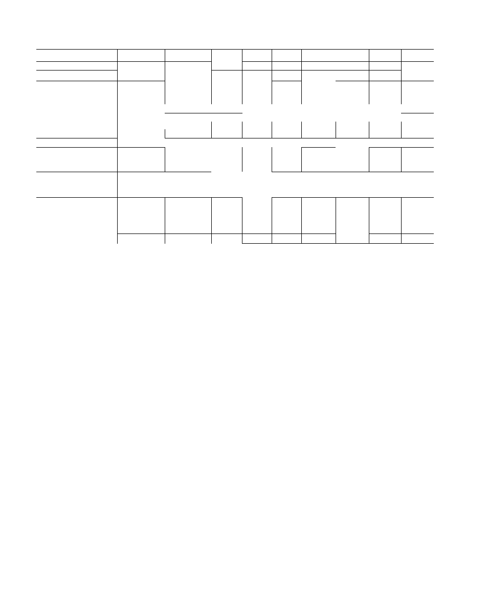
Table 2 — Physical Data
UNIT
48DL002
48DH002
48DL003
48DL004
48 DM004
48DH004
48DL045
48DL005
48DH005
OPERATING WT (lb)
331
343
385
411
430
438
450
476
512
REFRIG (22) CHG (Ib-oz)
3.2
3 2
3.6
5 1
5 1
5 2
5 1
5 1
COMPRESSOR
M27 (1-ph)
M27 (1-ph)
M34
M40
M40
M40
P46
P53
P53
AHbbz^/h(J-ph)
AH5527h(3-ph)
Cyl inders
2
2
2
2
2
2
2
2
2
Rpm (60-Hz)
3500
CONDENSER FAN
Propel ler-Typ e — Direct Drive; Vertical Disc
large
Air Quantity (Cfm)
1700
1700
2000
2500
2500
2500
2700
2700
2700
Motor Hp
Vs
Vs
Vs
Vs
Vs
Vs
Vs
V,
Vs
EVAPORATOR FAN
Centrifugal — Direct Drive; Horizontal Discharge
CAPACITY (1000 Btuh)
Г
Cool in g
24
24
30
36
36
36
42
48
48
Input Heotlng/Bonnet*
56/42
80/60
80/60
80/60
110/82 5
125/93 75
100/75
110/82 5
150/112 5
MAX EXTERNAL
STATIC PRESSURE
Heating (in. W.C.)
40
FILTERSt (1-in. thick)
Disposable — No. ..
1 15x20
1 15x20
1 15x20
1 20x25
1 20x25
Size (in.)
1 .20x25
1 20x25
2 15x20
1 20x20
1 20x20
1 .20x20
2 20x20
1 25x25
1 .25x25
Permanenti — No. ..
Size (in.)
1 15x20
1 15x20
1 20x20
1 20x20
1 20x20
1 .20x20
1 20x25
2 15x20
2 15x20
HEAT TEMP RISE (F)
35-65
45-75
35-65
35-65
35-65
45-75
35-65
35 65
45-75
* Ratings shown for elevations up to 2000 ft above sea level. For ele
vations above 2000 ft deduct 4% capacity for each 1000 ft above
sea level
i Recommended field-supplied filter
ifBased on 0.082 in. wg pressure drop or less thru filter at 520 ft/min
face velocity.
OUTSIDE AIR LIMITATIONS - Although there
are no restrictions on either the percentage or the
temperature of the outside air circulated thru the
unit, the rate of moisture condensation from the
combustion process increases significantly when
return air temperature drops below 50 F. Protect
the drain holes in the bottom pan against ice
buildup if outside air of below freezing tempera
ture is used
VIBRATION ISOLATION -- The unit compressor,
evaporator fan and condenser fan are mounted on
isolators to minimize vibration. Additional isola
tion is not required for slab mounting. With some
types of roof construction, however, the use of
field-furnished mbber pad type isolators may be
advisable.
Unit Rigging
1. Sling the unit perpendicularly to shipping skid
mnners. Use spreader bars to prevent damage
from sling or cable.
2.
Raise unit to desired location and remove
shipping skid.
3. Mount and level the unit as indicated in Unit
Support and Mounting section.
Unit Support and Mounting
LEVELING THE UNIT — Level the unit from end
to end but pitch the unit slightly (3/8 to 1/2 in )
towards the condensate drain on the service access
face of the unit (Fig. 1). Use the unit frame as a
leveling reference.
SLAB MOUNTING — Mount the unit on a
concrete pad, cement blocks, bricks or creosoted
wood of sufficient area and strength to support the
unit weight (Table 2) without distortion or damage
and maintain the drainage pitch recommended
above.
A gravel apron will prevent grass and foliage
from obstructing the condenser air inlet (Fig. 1).
FLAT OR RECESSED ROOF MOUNTING should
be as close as possible to the roof duct opening
Place the unit on at least 2 wooden 2x4 in. or
2x6 in. sleepers.
Sleepers may be perpendicular to or parallel to
the unit mounting rails, but must span at least 2
roof joists or purlins to distribute unit weight. Set
the sleepers in roof cement or mastic. Do not plug
drain
holes
in
the
compressor
or
furnace
compartment.
Do not support the unit by the ends of the base
rails, nor use vibration isolators at these points.
Unit will not be properly supported and could sag
in the middle.
PITCHED ROOF MOUNTING -- Constmct a
s t u r d y
w e l d e d
o r
b o l t e d
f r a m e o f
1-1/2
X
1-1/2
X
1/4 in. or larger angle iron, with
frame members at right angles to unit rails. Make
provisions for securing unit to frame. Use roof
cement or mastic where frame is in contact with
roof.
%