Never use an open ñame for leak testing, 208/l – Carrier 48DH User Manual
Page 4
Attention! The text in this document has been recognized automatically. To view the original document, you can use the "Original mode".
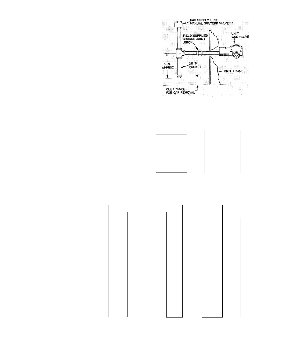
1. Furnish the gas line from the main gas supply
to the unit gas valve (Fig. 4).
2. Size the supply pipe for 0.3-in. wg maximum
pressure drop and for the volume of gas
required (Tables 3, 5 and 6). Pipe size must
equal or exceed size of gas connection at unit.
3. Use pipe dope approved for use with liquefied
petroleum (LP) gases.
4. Pitch all horizontal pipe runs towards the unit
1/4 in. per 15 ft to prevent trapping condensed
moisture.
5.
Support piping to maintain proper pitch,
prevent strain on unit controls, and prevent
accidental movement of piping.
6. Install a tee for attachment of a dirt and
moisture drip pocket (Fig. 4). Tee should be at
same level or below gas valve connection. Drip
pocket must be protected against freeze-up.
7. Install manual shutoff valve on gas piping per
local codes.
8. Provide a ground joint union in the gas supply
line near the unit gas valve.
9. Protect gas piping from freezing temperatures.
Gas stoppage can result from failure to insulate
pipe against wide or sudden temperature
changes.
10. When piping is completed, check entire gas
assembly and field piping with soap and water
solution.
Never use an open ñame for leak testing.
Fig. 4 — Gas Piping Details
Table 3 — Maximum Pipe Cap. (cfh)^
PIPE
NOMINAL PIPE SIZE
LENGTH (ft)
V.
V
/ 4
1
10
132
278
520
20
92
190
350
30
73
152
285
40
63
130
245
50
56
115
215
60
—
105
195
70
96
180
80
_
90
170
90
—
84
160
100
-
79
150
1
V
4
1050
730
590
500
440
400
370
350
320
305
*Cfh — Cu ft/hr based on 0.3 in. wg pressure drop and 0.6 gas
specific gravity.
NOTE;
Correction is not necessary for normal number of fittings nor
for 0.7 gas specific gravity unless specified.
Table 4 — Electrical Data (60-Hz)
UNIT
Model
Serie
48DL,DH
002
48DL
003
48DL,DH,
DM004
48DL
045
48DL,DH
005
200
300
400
200
300
400
500
^00
300
400
500
600
200
300
400
500
600^
200
300
400
500
600
VOLTAGE
Norn V/Ph
230/1
208/3
208/1
230/1
208/3
230/3
___ 460A3__
'^208/l~
230/1
208/3
230/3
460/3
208/1
230/1
208/3
230/3
460/3
'208/1^
230/1
208/3
230/3
460/3
UNIT
COMPR
OFM
WSA
FLA
ICF
FU
FLA
LRA
FLA
23 5
19 5
83 4
35
16 1
80 0
2 0
1 4
21 6
17 9
75 4
30
14 5
72 0
2 0
1 4
16 8
14 0
58 4
20
10 6
55 0
2 0
1.4
29 8
24 3
102.8
40
20.8
99 0
2 4
1 4
27 3
22.3
91 8
35
18.8
88.0
2 4
1 4
18.8
15 5
73 8
25
12 0
70 0
2 4
1 4
17 4
14 4
63.8
25
10 9
60.0
2 4
1.4
8.8
7 4
31 9
15
5 5
30 0
2.4
1 4
39 0
32 4
117 9
50
26 5
112,0
3 1 1
2.8
35 9
29 9
105 9
45
24 0
100 0
3 1
2.8
25 0
21 2
85 9
30
15 3
80 0
3 1
2 8
23 3
19 8
75 9
20
13 9
70 0
3.1
2 8
11.3
10.0
39.0
15
7 0
35 0
3 1
2.8
41 0
34 1
115 6
60
27 5
109 0
3 8
2.8
36 5
30 5
100 6
50
23 9
94 0
3 8
2 8
27.4
23 2
85.6
35
16 6
79 0
3 8
2 8
24 5
20 9
73 6
30
14 3
67 0
3 8
2.8
12 4
10 6
38 3
15
7 3
35 0
3 8
2 8
46 5
38 5
132.6
60
31 9
126 0
3 8
2.8
41 5
34 5
112 6
50
27 9
106 0
3 8
2.8
29 5
24.9
93.6
40
18 3
87 0
3 8
2 8
25 2
21.5
76 6
35
14 9
70 0
3 8
2 8
13 3
11.3
38 3
20
8 0
35 0
3 8
2.8
FLA — Full Load Amps
FU — Dual Element Fuse or Circuit Breaker having high inrush
capability (max allowable amps)
ICF — Max Instantaneous Current Flow during start-up is the sum
of compressor LRA plus the FLA of all other motors in
the unit.
IFM
LRA
OFM
WSA
Indoor (Evaporator) Fan Motor
Locked Rotor Amps
Outdoor (Condenser) Fan Motor
Wire Sizing Amps per NEC equals 1.25 x FLA of the largest
motor plus the sum of all other motors in the unit.