Start-up – Carrier 48DH User Manual
Page 6
Attention! The text in this document has been recognized automatically. To view the original document, you can use the "Original mode".
START-UP
Unit Preparation
— Do not apply power to the unit
before removing shipping supports as follows:
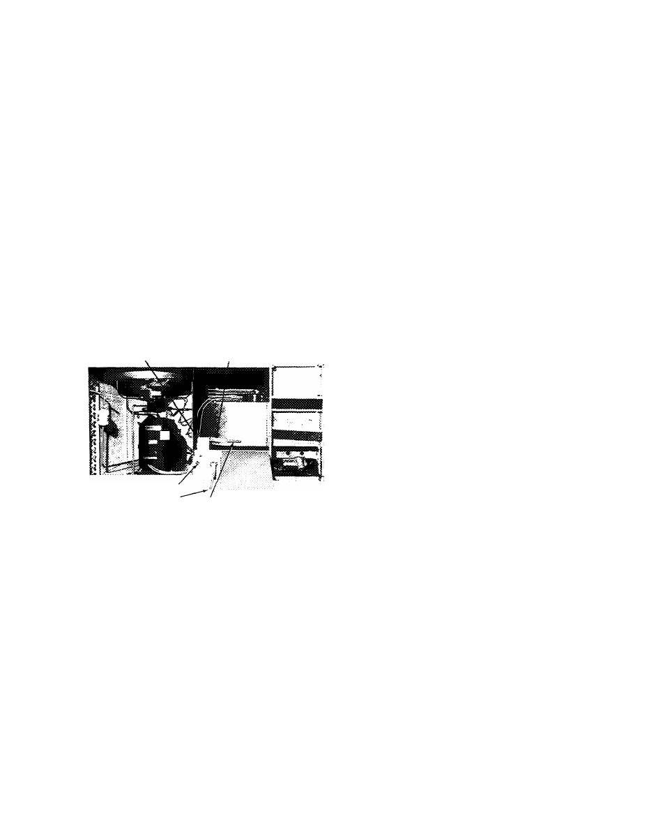
REMOVE BLOWER WHEEL SUPPORT (Fig. 6)
1. Remove heating section access panel.
2. Remove upper right side screw in control box
and swing control box downward as shown.
3. Loosen 5 screws and remove interior panel.
4. Loosen 3 motor bracket hold-down bolts by
about 1/8 in. (roughly 3 turns).
5. Grasp wooden slat (Fig. 6) with pliers and pull
slat out completely.
6. Swing hinged cover plate (Fig. 6) over slat hole
and secure with sheet metal screw.
7. Remove sheet metal screw holding outboard
blower housing support (Fig 6) and discard
support.
8. Check that blower wheel rotates freely. Do not
retighten
motor
bracket
hold-down
bolts
loosened in step 4.
9. Replace interior panel, control box and heating
section access panel.
OUTBOARD BLOWER
HOUSING SUPPORT
HINGED
COVERPLATE
CONTROL WIRING'
LINE WIRING'
!
—-CONTROL
WOODEN SLAT
Fig. 6 — Removal of Blower Wheel Support
REMOVE SHIPPING TAPE on condenser fan, if
not previously removed.
CHECK COMPRESSOR HOLD-DOWN BOLTS -
Compressor is internally spring-mounted. Do not
loosen or remove hold-down bolts.
SET HEAT ANTICIPATOR on thermostat at 0.6
amps for natural gas units, and at 0.4 amps for LP
gas units.
OPEN GAS SUPPLY LINE VALVE and purp line
by loosening ground joint union (Fig. 4). Tighten
union when gas odor is detected.
ADJUST BLOWER SPEED, if required, to main
tain heat temperature rise limits given in Table 2.
Change fan motor lead connection as shown on
label diagram.
CHECK AUTOMATIC PILOT
1. Turn power on.
2. Place thermostat selector switch at “Off’ and
set thermostat dial a few degrees below room
temperature.
3. Purge the gas supply line by loosening the
ground joint union (Fig. 4). Tighten the union
when gas odor is detected.
4. Remove the heating section access panel and
wait 5 minutes before proceeding.
5. Turn manual shutoff valve on main gas valve to
“Pilot” position.
6. Place thermostat selector switch at “Heat” and
set dial a few degrees above room temperature.
7. Pilot ignites.
8. Adjust pilot flame if not at the factory-set
length of 1-1/4 to 1-1/2 in. To adjust, remove
pilot adjusting screw cap on main gas valve (Fig.
8). Turn screw clockwise to increase and
counterclockwise to decrease flame length.
Replace cap.
If pilot does not ignite, gas pressure may be too
low. Refer to the applicable Start-Up Sequence for
required gas pressures.
If pilot fails to ignite on size 003 — 005 natural
gas units, check spark ignition system as described
in Service section.
NOTE: If pilot is extinguished for any reason,
ignitor will automatically attempt to rekindle
flame.
On size 002 units using natural gas, pilot
ignition is affected by the unit supply voltage.
Check the voltage and then adjust the glow coil
circuit as described below.
GLOW COIL PILOT ADJUSTMENT - On size
002 units using natural gas, an automatic-reset
circuit breaker cycles the glow coil on and off
during pilot ignition. To ensure proper pilot
ignition, the length of the resistance wire in the
glow coil circuit must be compatible with the
voltage in the circuit. This wire is tagged and coiled
on the casing at the left of the gas manifold.
Measure the line voltage to the unit. Compare
the measured voltage with the following ranges and
cut off the length of resistance wire indicated:
a b o v e 2 3 2
V,
n o n e ; 2 2 2 — 242v,
12in.;
212 — 232
V,
27 in.; 207 — 222 v, 36 inches. If the
measured voltage falls within 2 of these ranges, cut
off the shortest length.
If the thermostat wire is no. 18 gage, cut off
1 in. of resistance wire for each 2 ft of thermostat
cable length over 25 ft.
If other than no. 18 gage copper thermostat
wire is used, measure the resistance of one lead
from unit to thermostat. Multiply the resistance by
2. Then cut off resistance wire 1 in. per 0.032
ohms to equal the resistance of the thermostat
leads.