Typiccil wiring schematic, I 50df modu-pac – Carrier MODU-PAC 50DF User Manual
Page 34
Attention! The text in this document has been recognized automatically. To view the original document, you can use the "Original mode".
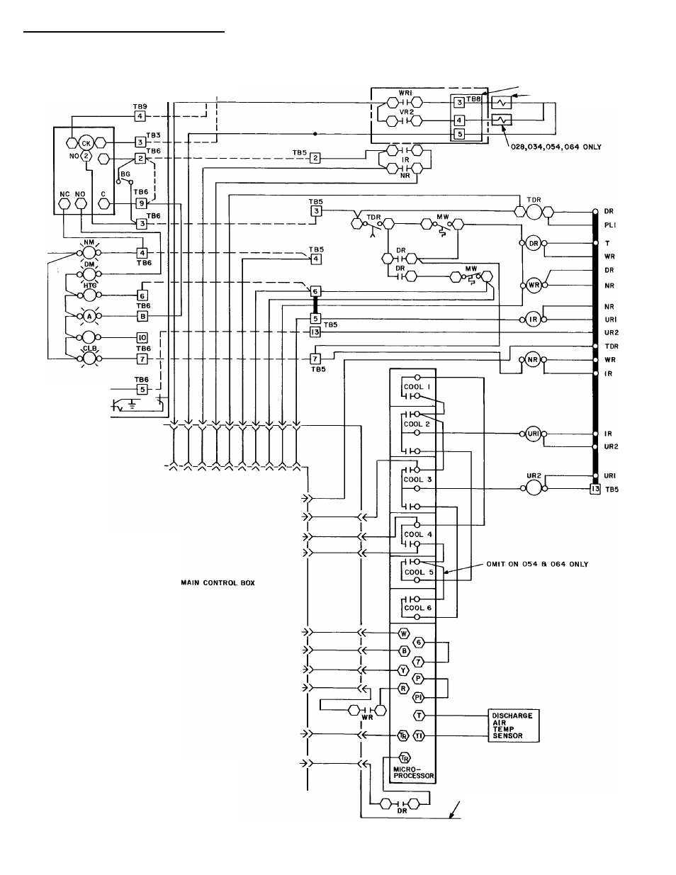
I 50DF Modu-Pac®
Typiccil wiring schematic
REMOTE CONTROL
BOX
FIELD
POWER SUPPLY
I ■
UNLOADER JUNCTION BOX
028,034,044,054,
064 ONLY
LEGEND
BS
— Bypass Switch
Ck
— Clock
CIg
— Cooling
DM
— Day Mode
DR
— Day Relay
Htg
— Pleating
IR
— Interlock Relay
MW
— Morning Warm-Up
NM
— Night Mode
NR
— Night Relay
PL
— Plug Assembly
TB
— Terminal Block
TDR
— Time Delay Relay
U
— Unloader
UR
— Unloader Relay
WR
— Warm-Up Relay
□
Terminal Block
o
Terminal (Unmarked)
O
Terminal (Marked)
Factory Wiring
Field Wiring
Plug
Receptacle
To indicate common potential only;
not to represent wire
VARIABLE VOLUME BOX
#
34
See also other documents in the category Carrier Conditioners:
- 42S (72 pages)
- 30GT (4 pages)
- 48SS060 (8 pages)
- 50ME (54 pages)
- 38AH024-034 (26 pages)
- ZC (28 pages)
- 30GA (12 pages)
- COMFORTLINK 48A2 (8 pages)
- 48HE003---006 (64 pages)
- 33ZCSECTRM (52 pages)
- 19XRV (40 pages)
- 17DA (8 pages)
- SINGLE PACKAGED ELECTRIC COOLING UNITS 50GS (28 pages)
- 48JZ (N) 024-060 (30 pages)
- 30GX080-176 (8 pages)
- 50DL (24 pages)
- 50GL-A (4 pages)
- NP034-074 (72 pages)
- 40GXQ (12 pages)
- 30XA080-500 (8 pages)
- 39E (12 pages)
- 40KMQ------301 (10 pages)
- 38AE (12 pages)
- 48AW (118 pages)
- 38GXQ (28 pages)
- 48ES---A (38 pages)
- 48GL (22 pages)
- 48GH (22 pages)
- 40QA024-060 (24 pages)
- TJF004 (52 pages)
- 39LD (40 pages)
- 48DL (4 pages)
- 48/50TC04---28 (44 pages)
- 50EJ (56 pages)
- 17EX (120 pages)
- 50BA (24 pages)
- 50BB (16 pages)
- 50BB (8 pages)
- 50BJ (20 pages)
- 30H (16 pages)
- 48HJD005-007 (48 pages)
- 50ZP (6 pages)
- 50DP016 (16 pages)
- 50LJ008-014 (19 pages)