Fsodfl, Ccsv, Typiccll wiring schematic – Carrier MODU-PAC 50DF User Manual
Page 18: Speed option shown)
Attention! The text in this document has been recognized automatically. To view the original document, you can use the "Original mode".
fsODFl
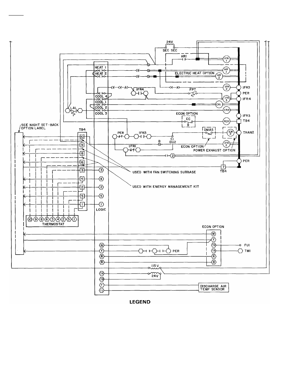
Typiccll wiring schematic
(2-speed option shown)
t
ccsv
CR
DM
DMAS
Econ
EMC
ENTH
FPT
Fu
Hr
IFC
IFM
IFR
IP
LAL
IPS
OFC
1182
Capacity Control Solenoid Valve
Control Relay
Damper Motor
Damper Motor Auxiliary Switch
■
Economizer
• Exhaust Motor Contactor
Enthaipy Control
■
Freezeup Protection Thermostat
Fuse
• Heater Relay
Indoor Fan Contactor
■
Indoor Fan Motor
• Indoor Fan Relay
• Internal Protector
Low-Ambient Lockout
■
Low-Pressure Switch
■
Outdoor Fan Contactor
OFM — Outdoor Fan Motor
PER
— Power Exhaust Relay
PI
- Plug
Sec
— Secondary
TB
— Terminal Block
TM
— Timer Motor
Tran
— Transformer
Q
Terminal Block
O
Terminal (Unmarked)
O
Terminal (Marked)
B
Terminal (Circuit Board, Factory
Connected)
18
(S
Terminal (Circuit Board, Field
or Accessory Connected)
Factory Wiring
Circuit Board Run
Option Wiring
Field Wiring
Splice
To indicate common potential only;
not to represent wire
Plug
Receptacle
i