50df, Electrical protection devices – Carrier MODU-PAC 50DF User Manual
Page 17
Attention! The text in this document has been recognized automatically. To view the original document, you can use the "Original mode".
50DF
As space temperature approaches the heating tempera
ture set point, heating stages cycle off.
During heating, economizer is limited to the minimum
position to provide minimum outdoor air for ventilation
requirements.
Operating
sequence
with
economizer
and
energy
management
Option/Accessory
(Using
electronic
thermostat or transmitter)
Clock in remote control box switches controls to DAY
(OCCUPIED) mode. Indoor air fan runs continually while
in DAY (OCCUPIED) mode.
If return air temperature is below the adjustable setting of
the morning warm-up thermostat, economizer remains
closed.
When return air temperature goes above the setting of
morning warm-up thermostat, economizer goes to adjust
able minimum position.
When thermostat calls for cooling and outdoor air
enthalpy is below setting of enthalpy controller, economizer
modulates open. (If outdoor air enthalpy is above enthalpy
set point, economizer remains at minimum position.) The
economizer acts as first stage of cooling, providing “free
cooling” with outside air. If outside air alone cannot satisfy
cooling requirements of conditioned space, economizer
cooling is integrated with mechanical cooling.
Compressor(s), working simultaneously with econo
mizer, will be staged on to meet cooling load.
As conditioned space temperature approaches the
thermostat’s cooling set point, stages cycle off, last stage
first. After all stages of mechanical cooling are off, econo
mizer modulates to minimum position.
During cooling cycle, a discharge air sensor senses dis
charge air temperature. If discharge air temperature drops
below 62 F, economizer starts to modulate toward minimum
position. At 50 F, economizer wil be at minimum position.
At end of the DAY (OCCUPIED) mode on the clock, unit
controls enter NIGHT (UNOCCUPIED) mode. Econo
mizer closes. Indoor air fan runs only on a call for heating
or cooling. The temperature controls go into a HEATING
SETBACK, COOLING SETUP or COOLING SHUT
DOWN mode.
The HEATING SETBACK is field selectable at the unit
for 5, 8, 12 or 15 F below set point on the room thermostat.
The COOLING SETUP is field selectable at unit for 5,8,
or 12 F above the set point on the room thermostat.
During the UNOCCUPIED mode, unit continues to use
economizer cooling first and then integrates economizer
cooling
with
mechanical
cooling
to
meet
cooling
requirements.
A 5-hour manual bypass timer is located in the remote
control box to provide for times when air conditioning is
needed during normally unoccupied hours.
Two-speed indoor fan option
The 2-speed indoor fan staging sequence is based upon
room demand. As the conditioned space requires cooling,
this cooling demand is transmitted from the room thermo
stat to the logic panel. Up to 4 stages of cooling can be
sequenced on to meet the demand from the conditioned
space.
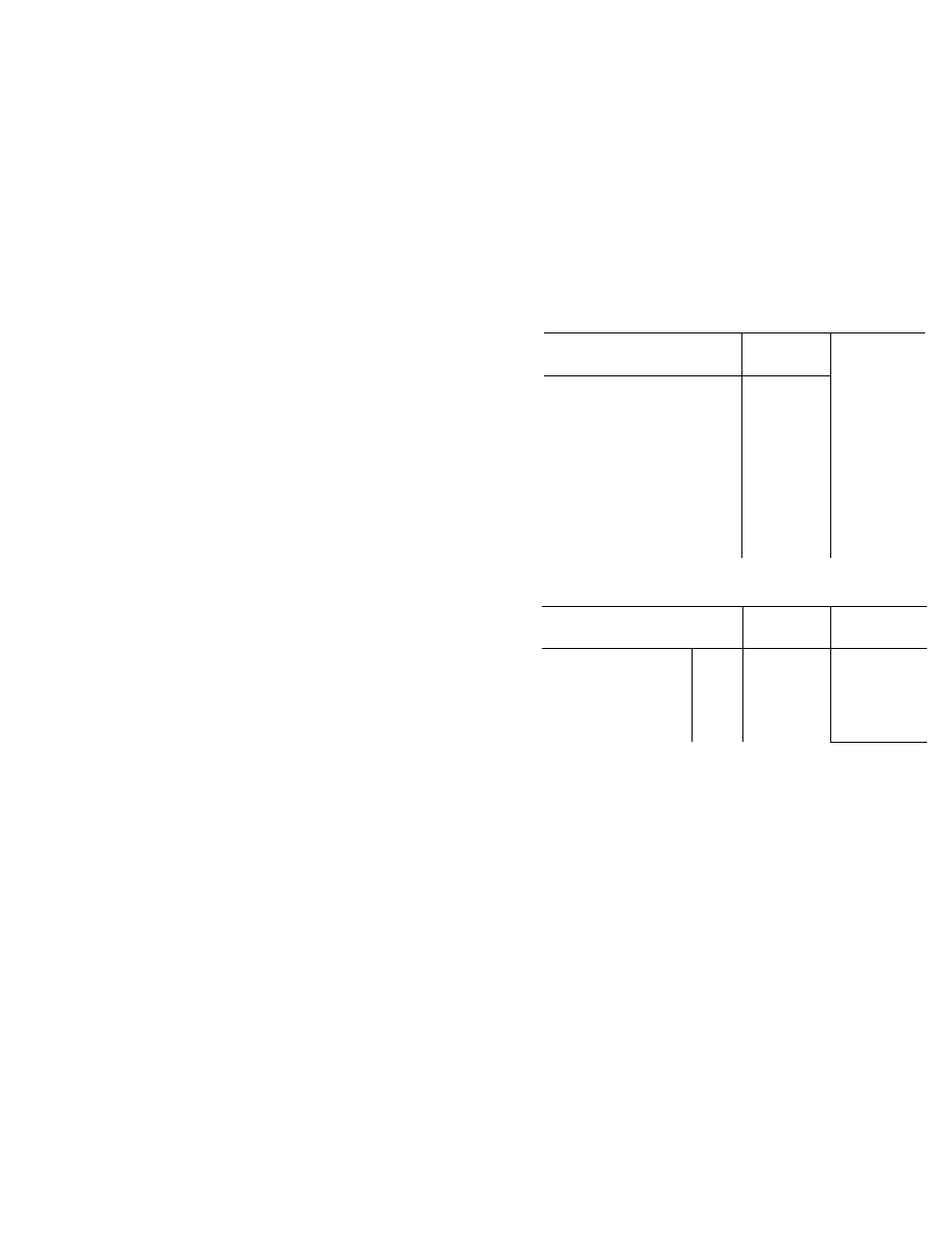
As shown in the 2-speed indoor fan staging tables, the
high fan speed is used only if and when needed.
When outdoor air enthalpy permits economizer opera
tion, the indoor fan runs at high speed only when necessary
to take maximum advantage of oufside air to provide cool
ing. Low speed is used when modulating economizer can
handle the cooling load.
When outdoor air enthalpy does not permit economizer
operation, the economizer dampers remain at minimum
position and the indoor fan motor runs at high speed only
when cooling is at its highest demand.
During HEATING mode, the fans operate at low speed
for ventilation only, and at high speed at all times during
active heating.
TWO-SPEED INDOOR AIR FAN STAGING
ECONOMIZER COOLING (Enthalpy Permitting)
.................................................................r
OPERATING
i
CONDITION i
FAN
SPEED
ECONOMIZER
DAMPER
POSITION
COMPRESSOR
OPERATtON
No Call for Cooling {
(Vent Air)
I
Low
Min
Position
Off
Step 1 1
(Call for Minimum Cooling) !
Low
Modulating
Between
Min and Full
Open
Off
Step 2
1
(Economizer Cooling) *
High
Full Open
Off
Step 3 1
(Integrated |
Econ /Mech Cooling) |
High
Full Open
Compr 1
Step 4
(Integrated |
Econ /Mech Cooling) |
High
Full Open
Compr and 2
MECHANICAL COOLING
(Enthalpy Not Permitting Economizer Cooling)
OPERATING
i
FAN
CONDITtON j SPEED
ECONOMIZER
DAMPER
POSnrtON
COMPRESSOR
OPERATiON
No Cali for Cooling
(Ventilation Air)
Step 1
Step 2
Step 3
Step 4
Low
Low
Low
Low
High“
Min Position
Min F*osition
Min Position
Min Position
Min Position
Off
'ofl
Compr 1
Compr 1 and 2
Compr 1 and 2
Electrical protection devices
Compressor circuit breakers, calibrated for specific
applications, are current sensitive and temperature com
pensated to shut off compressor if current draw is excessive.
Must be manually reset.
Inherent compressor thermal protection with auto
matic reset de-energizes control circuit if extreme motor
temperature should occur due to excessive suction gas
temperature or motor overloading.
Low-pressure switch automatically shuts off compressor
if refrigerant pressure drops below setting for loss-of-charge
protection.
Fusible plugs, located in refrigerant system, protect
against excessive pressures or temperatures in case of fire
or other abnormal high-temperature condition.
Inherent outdoor fan motor protection with auto
matic reset — Power circuit opens if motor temper^ure
becomes excessive.
Indoor fan motor circuit breakers — These manually
reset circuit breakers protect against fan motor overload.
Limit switches, heat limiters and overcurrent circuit
breakers provide thermal and overcurrent protection for
electric resistance heaters.
17