Cabletron Systems ELS100-24TXG User Manual
Page 18
4 Product Overview
ELS100-24TXG
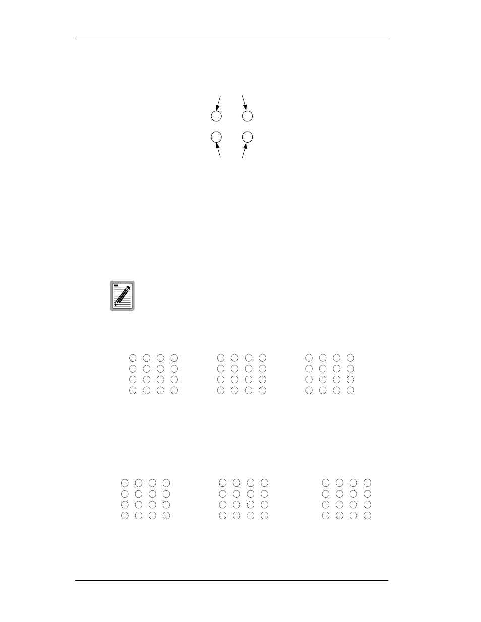
Figure 1-2 shows the Link and Activity LEDs for the 2 1000Base-X
Gigabit Ethernet ports. The LEDs are positioned to the left of their
associated port.
Figure 1-2. 1000Base-X Gigabit Ethernet Port LEDs
Figure 1-3 shows the Link and Activity port LEDs for 24 10Base-T/
100Base-TX ports (default configuration).
Pressing the front panel LED mode button changes the operation of the
RJ-45 LEDs to show Speed and Full Duplex operation, as shown in
Figure 1-4.
Figure 1-3. Port LEDs Default Configuration
Figure 1-4. Port LEDs LED Mode Button Pressed
The numbers above and below the port LEDs identify the
LEDs associated with a specific RJ-45 port.
Link LEDs
Activity LEDs
Link
2
3
4
5
6
7
8
1
Activity
Link
Activity
Link
10
11
12
13
14
15
16
9
Activity
Link
Activity
Link
18
19
20
21
22
23
24
17
Activity
Link
Activity
10/100 speed
2
3
4
5
6
7
8
1
Full/half duplex
10/100 speed
Full/half duplex
10/100 speed
10
11
12
13
14
15
16
9
Full/half duplex
10/100 speed
Full/half duplex
10/100 speed
18
19
20
21
22
23
24
17
Full/half duplex
10/100 speed
Full/half duplex