Front panel – Cabletron Systems ELS100-24TXG User Manual
Page 17
9032947
Product Overview 3
•
Software:
- Extensive diagnostics for product testing and troubleshooting
- Upgrades using the front panel console port or in-band with
TFTP
Front Panel
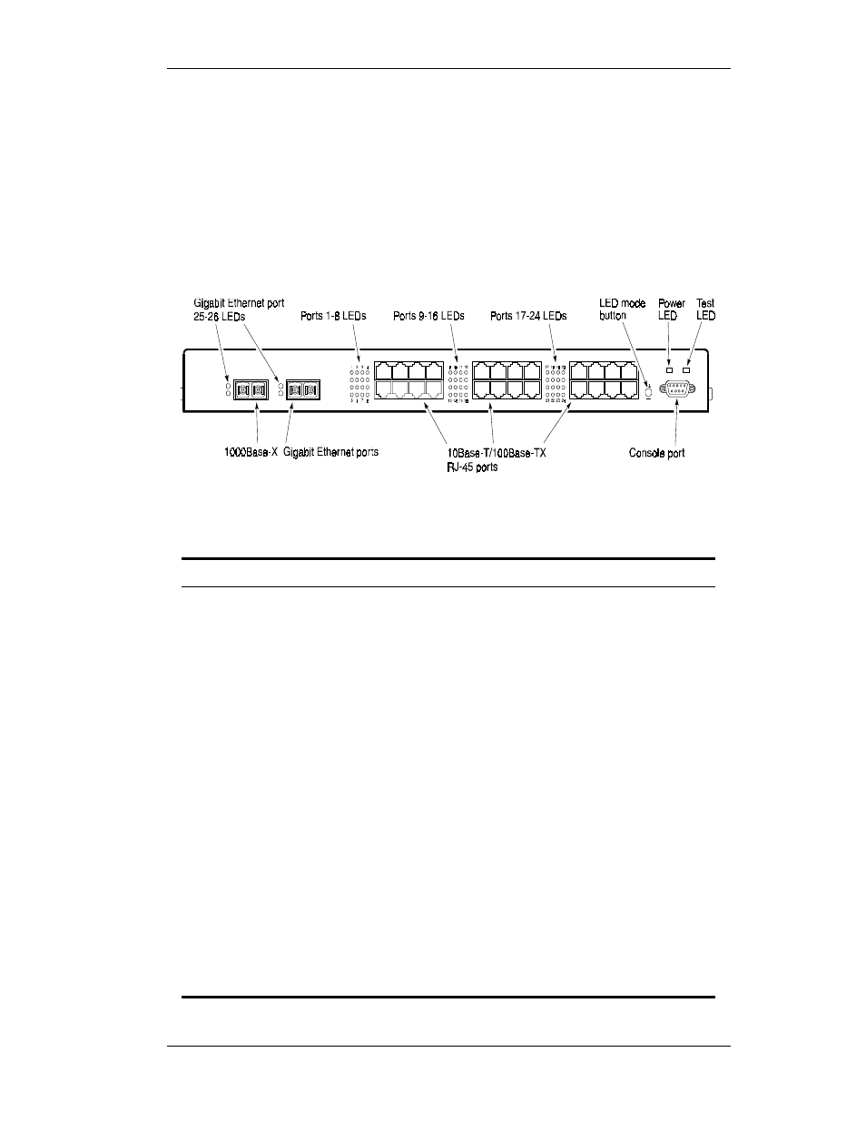
Figure 1-1 shows the front panel of the Cabletron ELS100-24TXG. Table
1-1 defines the ELS100-24TXG front panel components.
Figure 1-1. ELS100-24TXG Front Panel
Table 1-1. Front Panel Components
Name
Function
Gigabit Ethernet ports 25
and 26 LEDs
Indicates Link and Activity information (see Table 1-2
for details).
1000Base-X Gigabit
Ethernet ports
Gigabit Ethernet ports using GBIC modules.
Ports 1-24 LEDs
Indicates Link, Activity, Speed and Duplex information
(see Table 1-2 for details).
10Base-T/100Base-TX
RJ-45 ports
Copper ports using RJ-45 port connectors. These
ports are wired MDI-X.
LED mode button
Button used to switch RJ-45 port LEDs between Link/
Activity mode and 100M/Full Duplex mode. This button
has no affect on Gigabit Ethernet port LEDs.
Power LED
Lights steady green to indicate power is supplied to the
switch. Off indicates no power is supplied to the switch.
Test LED
Lights steady green after a reset and remains on until
successful completion of power-on self tests. Off indi-
cates a successful completion of the power-on self
tests.
Console port
Female DB-9 connector configured as a null modem
connection for serial out-of-band management using
the console menus.