2 measurement in pipelines, Measurement in pipelines -8 – YSI IQ SensorNet ViSolid Sensor 700 IQ User Manual
Page 20
3 - 8
ba76040e04
05/2014
Commissioning
ViSolid
®
700 IQ (SW)
3.4.2
Measurement in pipelines
If deposits occur on the pipe walls, the calibration should be repeated
at regular intervals.
Example:
45 ° pipe installation
The pipe should be straight for a length of approx. 25 cm beyond the
installation location. Angled or tapered pipes can cause interference
effects in the case of low levels of total suspended solids.
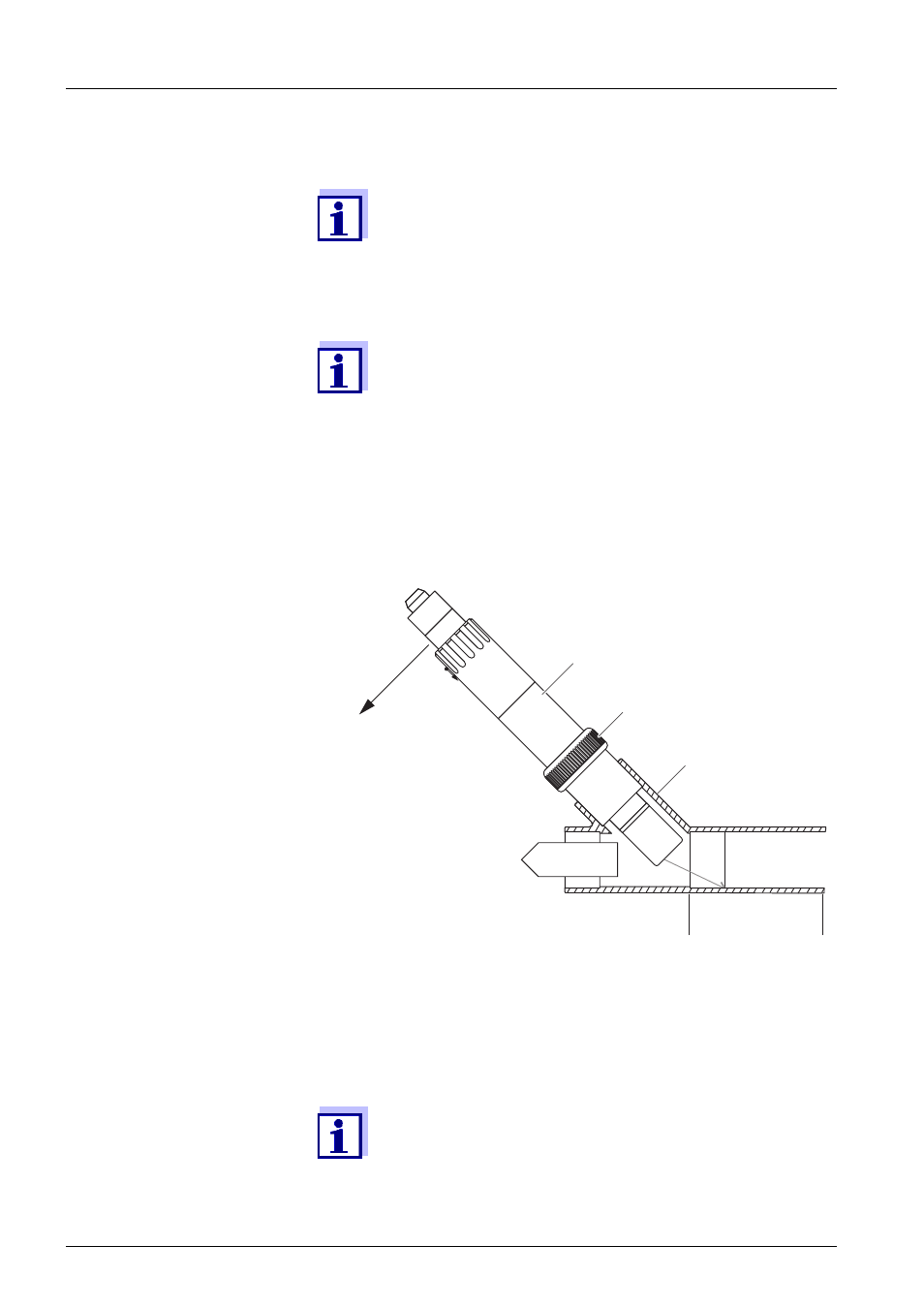
Fig. 3-5
Total suspended solids sensor in the pipe with EBST 700-DU/N flow-thru
adapter
Fig. 3-5 shows the installation of the EBST 700-DU/N flow-thru adapter
for installation in a pipeline (DN 50). The infrared beam points in the
opposite direction to the direction of flow. The marking on the sensor
points towards the pipeline (see Fig. 3-5).
If there is a low level of total suspended solids (< 2000 mg/
l SiO2 or < 1000 mg/l TSS), the effects of the measurement
environment can simulate a higher content of total sus-
pended solids. The effect of the measurement environment
can be reduced by ensuring the optimum conditions (see
section 3.3.2).
If an optimum installation is not possible due to the struc-
tural conditions at the measuring location (e.g. in narrow
pipelines), the effects of the measurement environment
can be compensated by user calibration (see section
4.2.4).
For exceptions to the direction of flow, see section
3.3.3 F
ADA-DF 9
EBST 700-DU/N
ca. 25 cm
straight pipe
Marking aid
in this direction
Swivel nut
Infrared beam
Direction
of flow