Accoppiamento elettrico, Electrical connections – Winco ECP3-2LN/2 (Replaces ECO3) User Manual
Page 22
ECP3 Manual - April 2011 revision 01
ACCOPPIAMENTO
ELETTRICO
L’accoppiamento elettrico e’ a cura dell’utiliz-
zatore finale ed e’ eseguito secondo la sua
sola discrezione.
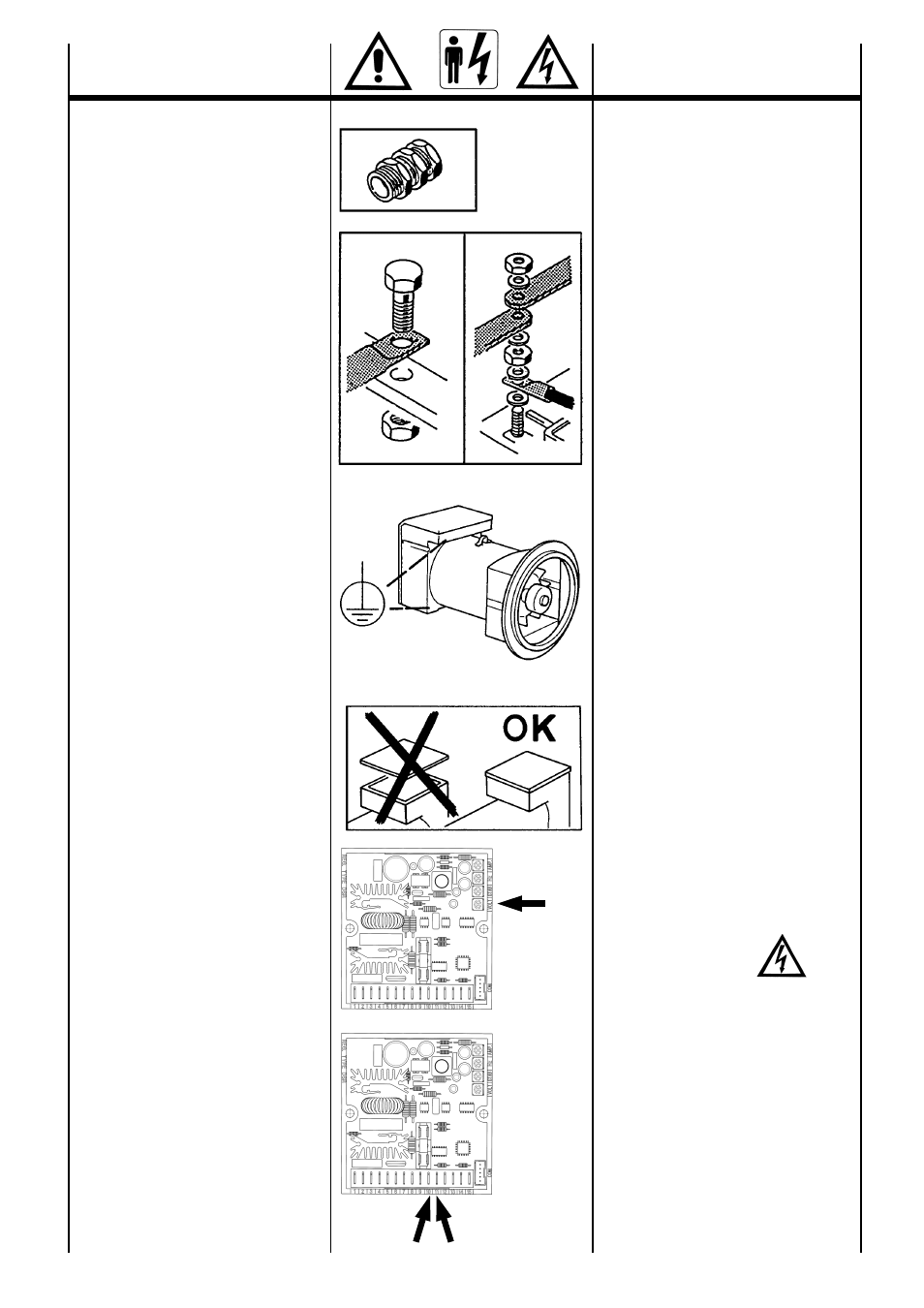
Per l’ingresso nella scatola morsetti si racco-
manda di utilizzare passacavi e serracavi in
accordo con le specifiche del paese di espor-
tazione.
Collegamento avvolgimenti
(tav. 3 pag. 39)
Sono previsti entrambi i collegamenti, stella
con neutro (Y) e triangolo (
∆) in tutti gli alterna-
tori.
Per passare da un collegamento Y a
∆ (es.da
400V a 230V) e’ sufficiente spostare i ponti
sulla morsettiera principale (vedere schema
tav. 3 pag. 39). Nessun intervento e’ richiesto,
sul regolatore di tensione.
I generatori sono costruiti di serie con 12 cavi
di uscita per consentire di ottenere tensioni
diverse (es. 115 / 200 / 230 / 400V ).
I generatori, vanno sempre collegati a terra
con un conduttore di adeguata sezione utiliz-
zando uno dei due (interno/esterno) appositi
morsetti.
Dopo aver eseguito il collegamento, rimontare
il coperchio scatola morsetti.
NOTA: variazioni di frequenza.
La macchina fornita per funzionare a 50Hz
puo’ funzionare anche a 60Hz (o viceversa); e’
sufficiente tarare il potenziometro al nuovo va-
lore nominale di tensione.
Passando da 50Hz a 60Hz, la potenza puo’
aumentare del 20% (corrente invariata), se la
tensione aumenta del 20%; se la tensione
rimane invariata la potenza, puo’ aumentare
del 5% per effetto della migliore ventilazione.
Per generatori costruiti appositamente per una
frequenza di 60Hz nel passaggio a 50Hz, la
tensione e la potenza devono necessaria-
mente diminuire del 20% rispetto a quelle rife-
rite a 60Hz.
REGOLATORE DI TENSIONE
(tav. 4 pag. 39)
L’autoregolazione ottenuta tramite il regolatore
elettronico tipo DSR garantisce in condizioni
statiche una precisione della tensione del ±
1% con qualsiasi fattore di potenza e con
variazione di velocita’ compresa fra -10% e +
20%.
ATTENZIONE :
Il controllo di tensione va eseguito a vuoto con
l’alternatore funzionante a frequenza nomi-
nale.
Agendo sul potenziometro tensione dei re-
golatori elettronici si puo’ ottenere la regola-
zione della tensione entro il ±5% del valore
nominale.
E’ anche possibile, inserendo un potenzio-
metro da 10K
Ω negli appositi morsetti (10-11),
ottenere la regolazione della tensione entro il ±
5% del valore nominale.
Per maggiori dettagli sui regolatori consultare il
manuale specifico.
22
ELECTRICAL
CONNECTIONS
All electrical output connections are the re-
sponsibility of, and are at the discretion of, the
end user.
When making terminal box connections, all
cable and terminal lugs should meet the rele-
vant standards of the country of final destina-
tion.
Windings connection
(table. 3 pag. 39)
All alternators feature both star with neutral(Y)
and delta (
∆) connections.
To reconnect from a star to delta connection
(for ex. from 400V to 230V), modify the linking
arrangements on the output terminal board
(see diagram on table 3 page 39).
It is not necessary to adjust the voltage regula-
tor.
Standard alternators are equipped with 12 ca-
bles to offer different voltages (for example
115 / 200 / 230 / 400).
The alterrnator must always be earthed by
sufficiently rated cable, using one of the inside
or outside terminals. After completing output
connections, ensure that the terminal box co-
ver is securely in place.
NOTE : frequency variations.
A standard production machine wound for 50
Hz can also function at 60 Hz (and vice versa)
by resetting the A.V.R. voltage potenziometer
to the new nominal voltage value.
When changing from 50 to 60 Hz the alterna-
tor power, and nominal voltage will increase by
20%, but the current does not change from 50
Hz value. Should voltage stay at 50 Hz nomi-
nal value, then the output power may be incre-
ased by 5% due to improved ventilation.
For machines wound for 60 Hz, changing to
50 Hz, the voltage and power values have to
decrease by 20% of 60 Hz values.
VOLTAGE REGULATOR
(table 4 page 39)
Self-regulation by means of an DSR electronic
regulator guarantees precise voltages of ±1%
in static conditions with any power factor and
with a variation in speed of between -10% and
+20%.
PLEASE NOTE :
The generator output voltage must be
checked under no-load conditions, with the
correct setting of frequency.
The voltage may be adjusted by ± 5% of the
nominal, by acting upon the voltage potenzio-
meter on the electronic regulators.
By connecting a 10 K
Ω potentiometer across
the relevant terminals (10-11), it is possible to
have a remote voltage regulation of ± 5% of
nominal voltage.
For further details on regulators, please see
the specific manual.
VOLT
10 -11