Assembling the pump head – VACUUBRAND BVC professional G User Manual
Page 58
➨
Position any washers that are present be-
tween diaphragm support disc and connec-
tion rod.
➨
Screw diaphragm clamping disc, diaphragm,
diaphragm support disc, and washers to con-
necting rod.
➨
Bring the diaphragm into a position in which
it is in contact with the housing and centered
with respect to the bore so that it will become
clamped uniformly between housing and
head cover.
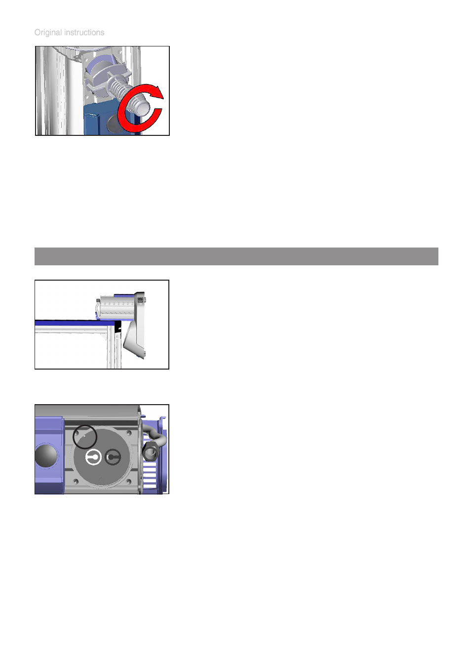
Assembling the pump head
➨
Assemble head cover and valves.
+
Pay attention to the correct position of the
guidance pin in the head cover (circle in fig-
ure)!
+
Pay attention to
correct orientation of the
valves (see figure):
Inlet side of pump head (black valve): The
valve tongue points at the kidney-shaped or-
ifice in the valve seat.
Outlet side of pump head (white valve): The
valve is oriented the opposite direction as
the valve at the inlet side. Round orifice un-
der the valve tongue.
➨
Lay down the BVC on the side of the pump,
e. g., at the edge of a workbench; support if
necessary.