USL CM-10 User Manual
Page 7
- 7 -
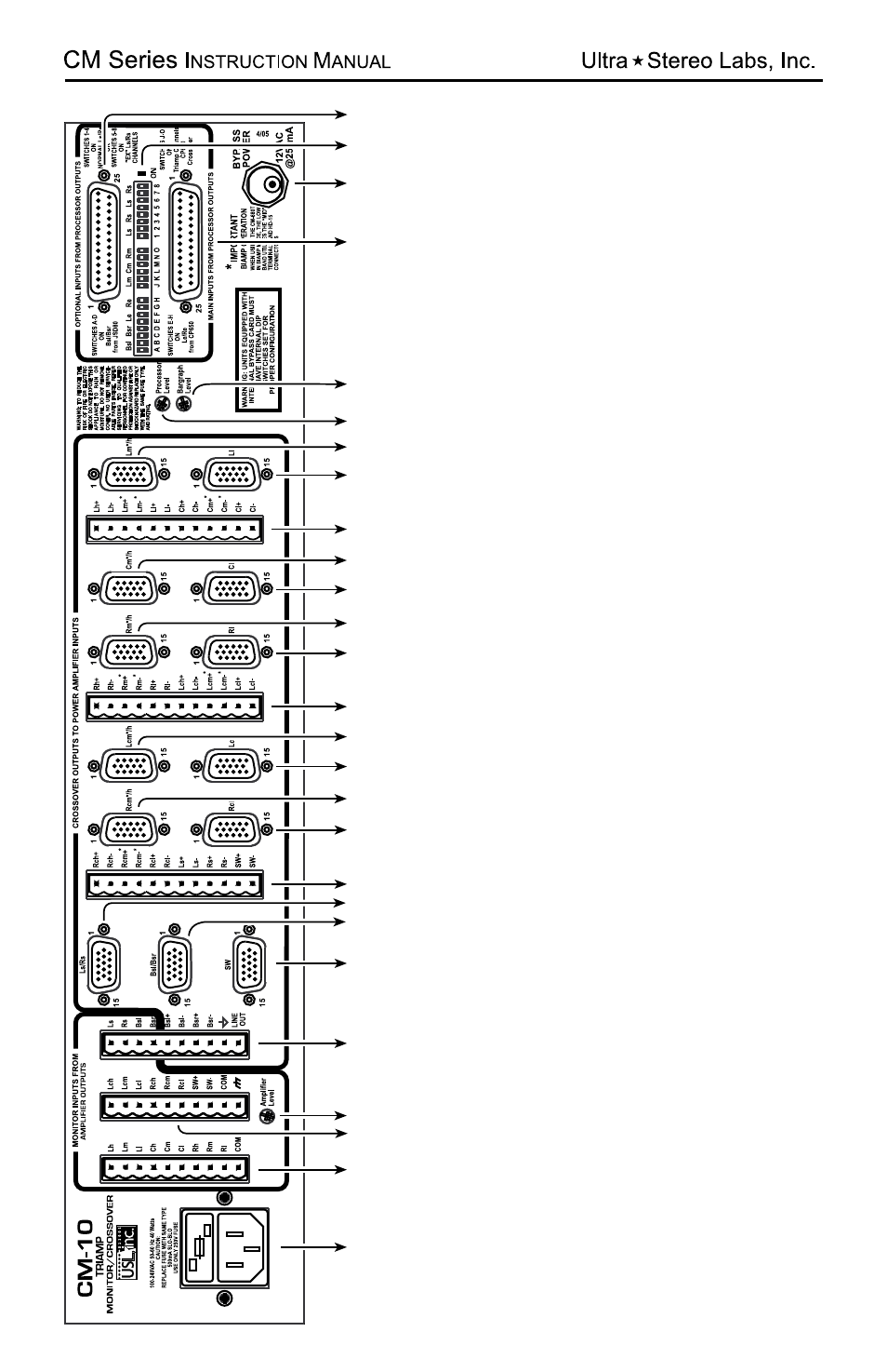
1. Main
AC connector with fuse.
2. Input
s from
Amplifier output
s - connect to the
power amplifier speaker output
s corresponding to
Lh, Lm, Ll, Ch, Cm, Cl, Rh, Rm & Rl channels and
COM.
3. Input
s from
Amplifier output
s - connect to the
power amplifier speaker output
s corresponding to
Lch, Lcm, Lcl, Rch, Rcm, Rcl, SW+, SW
- channels,
COM and Chassis ground.
4.
Amplifier level - this trimpot adjust
s the sensitivity
of the front p
anel Bargraph meter and Line Out
when in
Amplifier mode.
2
3
4
5
6
7
8
9
11
12
13
14
21
20
17
18
19
10
16
15
1
22
23
24
25
26
15. HD-15 connector - connect to Rl amplifier
.
16. HD-15 connector - connect to RM*/h amplifier
.
17. HD-15 connector - connect to Cl amplifier
.
18. HD-15 connector - connect to Cm*/h amplifier
.
19. Crossover output
s - connect to the power amplifier
input
s corresponding to Lh+, Lh-, Lm+*, Lh-*, Ll+, Ll-,
Ch+, Ch-, Cm+*, Cm-*, Cl+ & Cl- channels.
20. HD-15 connector - connect to Ll amplifier
.
27
1
15V
230V