Setting dip switches, Specifications – USL CM-10 User Manual
Page 15
- 15 -
Specifications
Inputs
Processor Main (female D-25): Ten balanced line inputs corresponding to
Left, Left center, Center, Right center, Right, Surround left, Surround right,
Back surround left, Back surround right and Subwoofer. Input impedance is
15k .
Processor Optional (male D-25): Ten balanced inputs corresponding to Left
extra/mid/center, Right extra/mid/center, Surround left, Surround right, Left
high, Center high, Center mid, Right high, Back surround left and Back surround
right.
All input impedances are 15k .
Outputs
Phoenix type: Twenty balanced line outputs corresponding to Left hi, mid and
lo, Left center hi, mid and lo, Center hi, mid and lo, Right center hi, midand
lo, Right hi, mid and lo, Surround left, Surround right, Back surround left, Back
surround right and Subwoofer.
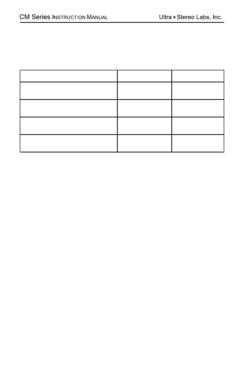
Setting DIP Switches
Channel
Configuration
Processor
JSD-80/XD-10P
CP-650
*
L, C, R, SW plus Ls/Rs channels
L, C, R, SW plus Ls/Rs, Bsl/Bsr
“EX” channels
L, Lc, C, Rc, R, SW plus Ls/Rs
channels
L, Le, C, Re, R, SW plus Ls/Rs
channels
L, Le, C, Re, R, SW plus Ls/Rs,
Bsl/Bsr, “EX” channels
1-4 ON
1-4 ON, A-D ON
1-4 ON
1-4 ON
N/A
1-4 ON
5-8 ON
N/A
1-4 ON, E-H ON
5-8 ON, E-H ON
**
NOTE1:
Lc & Rc are full band channels, Le/Re are low frequency channels
*
To use CP-650’s internal crossover in triamp mode, set switches J-D ON
**
Not possible with CP-650’s internal crossover in triamp mode.