USL CM-10 User Manual
Page 6
- 6 -
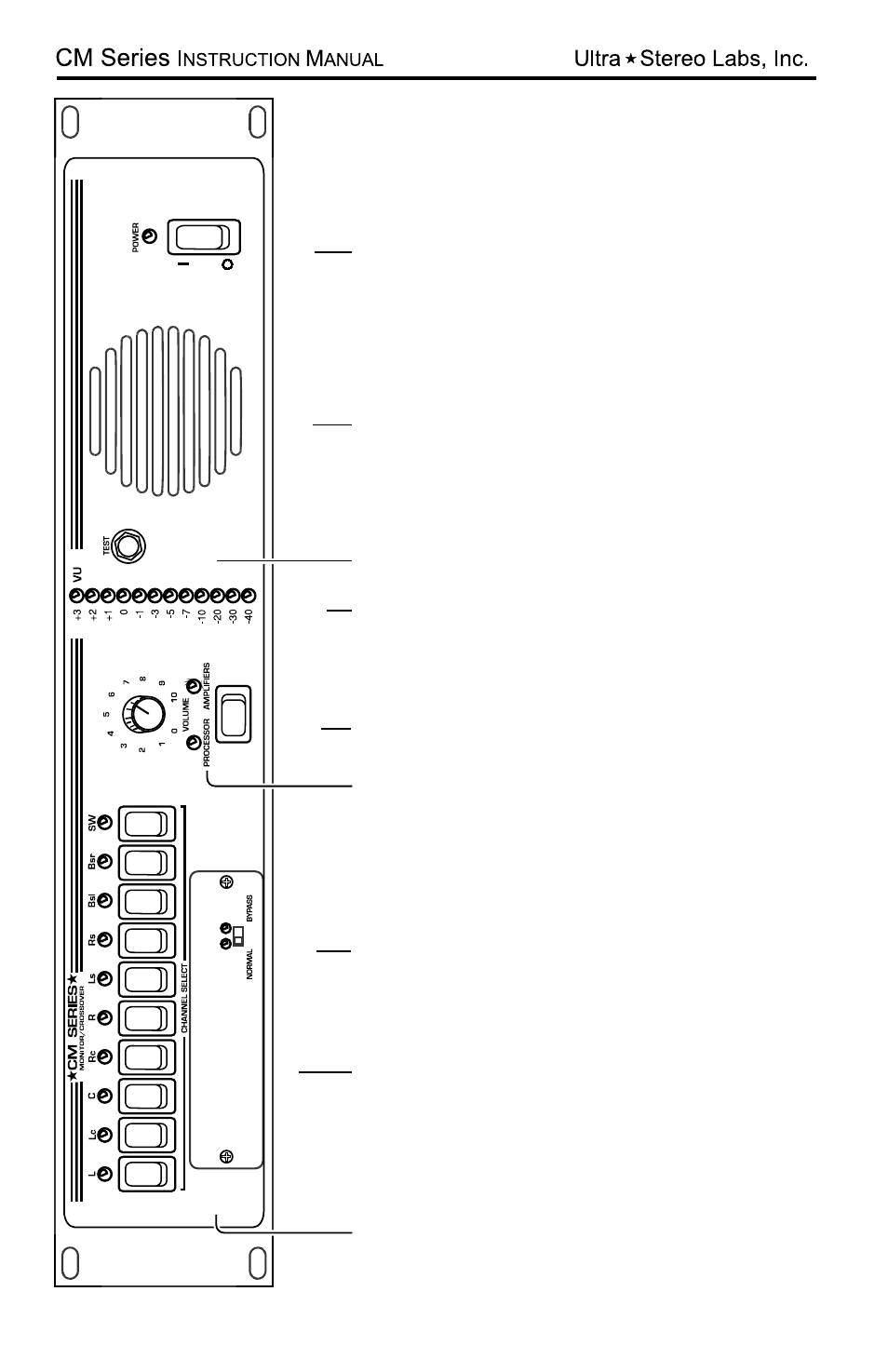
1. Channel select buttons - pressing a Channel Select Button ca
uses the corresponding LED to illuminate
and the signal from that channel to be monitored. Any combi
nation of ten channels can be selected.
2. Internal Digital or Analog Crossover Access Cover
.
3. Crossover Bypass Switch - Switching this will cause the inte
rnal crossover to be bypassed or engaged
and the condition will be indicated by its appropriate LED.
4. V
olume Control - controls the volume of the internal speaker and
test jack (7). The volume control
has no ef
fect on the VU Bargraph display
.
5. Processor/Amplifier Selector Switch - selects either the inp
uts from the cinema processor or power
amplifiers for monitoring.
6. VU Bargraph - displays the level of the selected channels. T
he VU Bargraph may be calibrated by
the rear panel trim adjustment (Figure 2). The VU Bargraph
operates independently of the volume
control (4).
7. T
est Jack - permits monitoring of the audio output of the CM Seri
es. Inserting a mono or stereo 1/4”
phone plug here disables the internal speaker and routes th
e audio output to the T
est Jack. Do
not connect any device here with less than 8 Ohms impedance
.
8. Internal Speaker
9. Power Switch
1
2
3
4
5
6
7
8
9