Hardware setup – USL PSA-200U User Manual
Page 8
Page 8
USL, Inc.
PSA-200U Instruction Manual
1st Edition. October, 2004
Hardware Setup
The laptop computer, the USB Interface Box
and the Power Adapter are usually set up
in the projection booth of the theater, while
the camera may be set up in either the audi-
torium or the projection booth. If the cam-
era is set up in the center of the auditorium,
the camera sees the movie screen exactly as
the audience does. (The PSA-200U camera
should be positioned at least one screen
width back from the screen.) If the camera
is set up in the projection booth, looking
through the projection port, compensation
for the vertical angle-of-view can be made in
the software (see Camera on page 15).
NOTE: The software must be installed be-
fore the USB cable is inserted into the laptop
computer.
NOTE: The Power Adapter will accept any
50 or 60 Hz power source from 100 to 240
VAC. The power cord itself is specific to the
region and type of outlet connector.
1. The power cord of the power adapter
should be disconnected during hard-
ware set-up.
2. Mount the camera on the tripod and
set it either in the center of the audi-
torium or in the projection booth.
3. Connect the camera cable from the
camera to the USB Interface Box.
4. Connect the female DC output con-
nector of the power supply to the
PSA-200U USB Interface Box.
5. Connect the AC power cord of the
Power Adapter to the Power Adapter
and to an AC outlet.
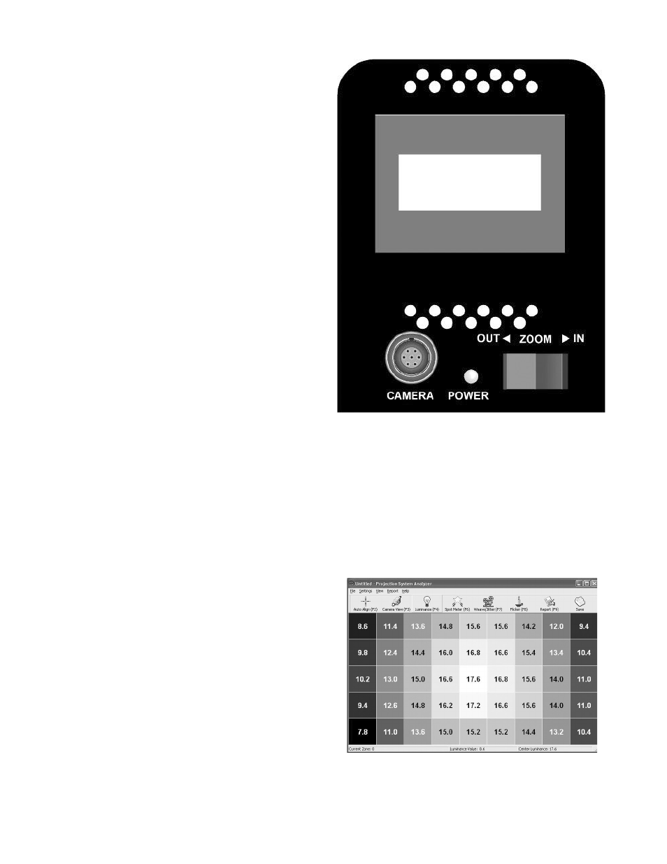
6. Remove the lens cap from the camera
lens, orient the camera and adjust the
zoom control at the rear of the camera
(see Fig. 1) so that the movie screen
fills about 90% of the camera view-
finder screen and is centered. (It may
be necessary to turn on the projection
lamp to provide adequate light for the
camera positioning and zoom adjust-
ment.)
(Fig. 1) Viewfinder Display
7. Turn on the laptop computer.
8. Access the PSA.exe program on the
laptop computer. The laptop computer
display should show a 9 by 5 grid of
luminance values (see Fig. 2). Across
the top will be a toolbar with function
key buttons which access various PSA-
200U functions.
(Fig. 2) Luminance Grid (9x5)