USL PSA-200U User Manual
Page 12
Page 12
USL, Inc.
PSA-200U Instruction Manual
1st Edition. October, 2004
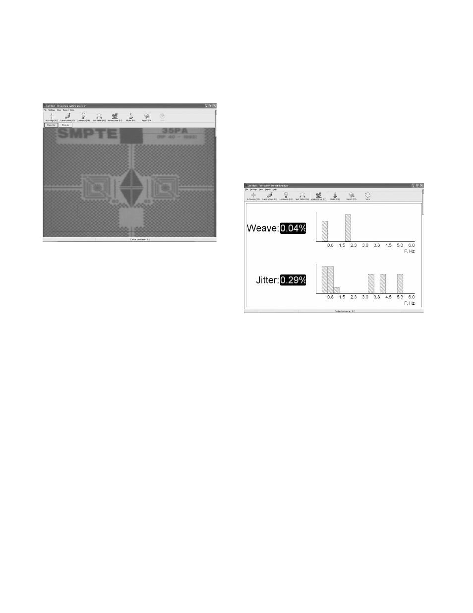
6. Use the Camera View [F3] zoom con-
trol to zoom in on the image until the
wide pattern in the center of the frame
fills nearly 3/4 of the Camera View in
the horizontal direction. (See Fig. 7.)
(Fig. 7) SMPTE Test Pattern
7. Press F7, or click on Weave & Jitter,
then press F3, or click on Camera
View. A small red box will appear at
the lower left of the laptop screen.
This box indicates the area which the
software analyzes in making the mea-
surements. Two aspects of this box
are important: (a) that it enclose only
the checker-board-squares portion of
the pattern and does not include any
other graphics; and (b) the camera
lens should be zoomed in far enough
that the box encloses approximately
three or four squares vertically.
8. Switch back to F7 to make the mea-
surements. After approximately 10 to
20 seconds, the display should appear
and present the initial readings (See
Fig. 8). Depending on the length of
the loop and the misalignment at the
splice, it will take from one to four
minutes for the results to reach the
final values asymptotically
9. Our research has shown that the PSA
will present stable, consistent read-
ings within one minute from a 20-foot
test loop. It can take up to four or five
minutes for final values to be reached
when shorter loops are used.
10. The PSA-200U is calibrated for use
with SMPTE test film RP 35-PA/ RP-40
for 35mm projectors. If measurements
are made using SMPTE 70-PA film on
70mm projectors, the weave and jitter
readings will be 10% higher than the
actual values.
11. Press or click on the Save bar at the
upper right of the screen to save the
figures to the report.
(Fig. 8) Weave
Checking Flicker (Optional Feature)
1. To measure flicker of the light source,
the projector should be running with-
out film in the gate. The screen image
should fill 90% of the raster in “Camera
View” (F3).
2. Press F8, or click on Flicker (see Fig. 9).
This function displays the flicker as
a percentage of the amplitude of the
desired component (the 48 or 72 light
pulses per second component). The
graph displays the frequency and am-
plitude of the flicker components as a
troubleshooting aid.
3. Flicker values of 1% to 3% are normal.
Readings of 5% or more usually indi-
cate a problem related to the Xenon
bulb or lamp house.