Twin City Fans With CE Mark - ES-2-06 User Manual
Page 8
8.
Twin.City.Fan.Engineering.Supplement.2-06
Grouting
Grouting. is. the. final. installation. step.. Check. all. shims.
before. grouting. to. make. sure. that. the. fan. is. resting.
evenly.on.all.points.with.anchor.bolts.secured.to.hold.
the. shim.. Use. forms. with. sufficient. space. allowed. for.
working. the. grout.. The. concrete. foundation. should. be.
clean. and. well. moistened. before. pouring. grout.. Use. a.
commercial.grade.non-shrinking.grout.and.be.especially.
sure.when.pouring.grout.that.the.anchor.bolt.sleeves.are.
filled..Refer.to.Figure.2.for.a.detail.of.a.proper.founda-
tion,.grout.allowance.and.anchor.bolt.sleeves.
Drive Mounting
Mount.drives.as.follows:
1..Slip. (do. not. pound). proper. sheave. onto. correspond-
ing.shaft..
CAUTION:.Placing.fan.sheave.on.motor.can.
overspeed.wheel.and.cause.structural.failure.
2..Align. sheaves. with. straightedge. extended. along.
sheaves. (see. Fig.. 5),. just. making. contact. in. two.
places. on. outside. perimeters. of. both. sheaves.. This.
“four-point”. alignment. may. also. be. checked. with. a.
string. tied. to. the. shaft. behind. one. of. the. sheaves..
The.string.is.then.pulled.taut.over.the.faces.of.the.
sheaves. to. check. the. alignment. at. the. four. points.
at. the. outside. perimeters.. Each. sheave. should. be.
rotated. about. one-half. revolution. during. this. check.
to.look.for.excessive.runout.or.a.bent.shaft..Parallel.
alignment.should.be.within.5mm.per.meter.of.center.
distance..Angular.Misalignment.should.be.less.than.1.
degree.
3..Install. and. tighten. the. belts.. Proper. belt. tension. is.
specified. on. the. included. documentation.. Belts. are.
tensioned.as.follows:
Post. type,. saddle. base,. slide. rails,. and. slide. base.
types.use.one.or.more.bolts.held.by.retaining.nuts.to.
adjust.the.motor.position..Loosen.the.retaining.nuts.
and.adjust.the.bolts.to.push.or.pull.the.motor.until.
the. belts. reach. their. specified. tension.. Tighten. the.
retaining.nuts.per.torque.specifications.in.Table.1.
4..Run. the. drive. for. a. few. minutes. to. seat. the. belts..
When.tightening.the.belts,.slide.the.motor.in.to.slip.
the.belts.on..Do.not.use.a.pry.bar,.as.this.may.dam-
age.the.belt.cords..Retighten.the.belts.to.the.proper.
tension.if.necessary..Recheck.sheave.alignment.
5..After. initial. installation. of. belts,. recheck. belt. tension.
and.alignment.as.indicated.in.Table.7.
Flexible Couplings
These. instructions. are. general. for. the. installation. of.
several. types. of. flexible. couplings. and. should. not. be.
used. as. a. substitute. for. more. specific. manufacturer’s.
instructions..The.coupling.manufacturer’s.installation.data.
is.included.with.the.supplied.datasheet.(when.applicable).
and. will. give. specific. dimensions. for. alignment. limits,.
lubricants,.etc..
. Before. preparing. to. mount. the. coupling,. make. sure.
that.all.bearings,.inlet.vanes,.shaft.seals,.or.other.com-
ponents.have.been.installed.on.the.shaft.
. When. mounting. and. keying. the. coupling. halves. to.
the. shaft,. follow. supplied. instructions. for. heating. and.
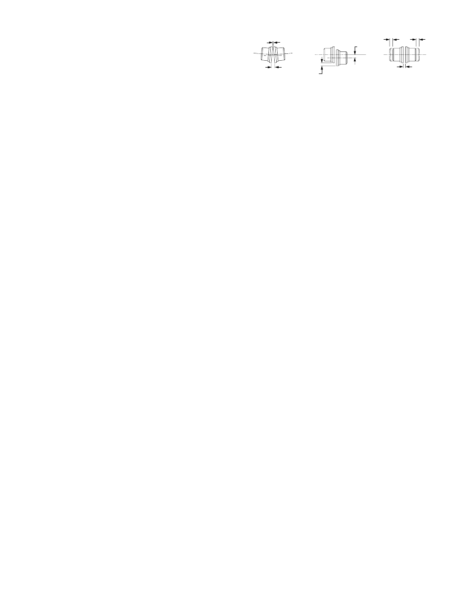
shrink.fitting..Set.the.coupling.halves.for.the.normal.gap.
specified.by.the.manufacturer..Coupling.gap.is.illustrated.
in.Figure.6.
. The.two.types.of.misalignment.are.illustrated.above..
Typically.angular.alignment.is.checked.with.feeler.gaug-
es.between.the.hub.faces..When.angular.alignment.has.
been. adjusted. to. manufacturer’s. specification. by. shim-
ming,. if. necessary,. parallel. alignment. can. be. checked.
with.a.straightedge.and.feeler.gauges.on.the.hub.halves’.
O.D.. When. shimming. has. brought. parallel. alignment.
within. specification,. angular. alignment. and. gap. should.
again.be.checked,.and.adjustments.made.if.necessary..
A. dial. indicator. may. be. used. to. more. accurately. take.
the.measurements.described.above.
. Special.adjustments.may.need.to.be.made.for.cou-
plings.used.with.some.equipment..As.an.example,.when.
used.with.motors.of.over.300.HP,.couplings.may.require.
provisions.for.limiting.end.float..Larger.drivers.may.grow.
in.operation.(due.to.heat.expansion).requiring.the.driver.
side.to.be.set.slightly.low.when.not.operating..Specific.
instruction. manuals. or. assembly. drawings. will. indicate.
these.requirements.when.applicable.
. Thoroughly.clean.the.coupling.halves.after.completion.
of.alignment..Reassemble.the.coupling.and.tighten.bolts,.
washers.and.locknuts..Lubricate.per.manufacturer’s.rec-
ommendations.
Duct Connections
The. fan. support. structure. is. normally. not. designed. to.
carry.loads.imposed.by.the.weight.of.ducts,.silencers,.
stacks,. etc.. Supporting. these. loads. on. the. fan. can.
cause. housing. distortion. and. may. cause. performance.
problems. due. to. the. relation. of. fan. housing. to. wheel..
Use.of.flexible.connections.is.recommended.
. Where. hazardous. materials. will. be. conveyed. in. the.
fan,. all. connections. made. by. the. user. shall. be. com-
pletely.sealed.with.material.suitable.for.the.gas.or.vapor.
to.be.handled.
Guards and Enclosures
When. advised. of. the. need. for. guards. fully. complying.
with.the.machinery.directive,.Twin.City.Fan.Companies,.
Ltd..will.supply.the.guarding.identified.as.being.required..
In. most. cases,. Twin. City. Fan. Companies,. Ltd.. is. not.
aware.of.the.end.use.and.installation.of.the.fan,.which.
typically.eliminates.the.need.for.more.restrictive.guard-
ing.to.be.compliant.with.EN.294.and.EN.811..For.this.
reason,.the.user.is.must.verify.that.the.final.installation.
is.compliant.with.EN.953,.EN.294,.and.EN.811..This.is.
especially.true.of.plug.and.plenum.fans..Specific.items.
that. should. be. considered. include. but. are. not. limited.
to.the.following:
•. Outlet ducting / enclosure..The.ducting.or.enclosure.
must.be.compliant.to.the.requirements.of.EN.953.
and.EN.294.and.EN.811..This.is.not.assured.by.
Twin.City.Fan.Companies,.Ltd..unless.specifically.
notified.by.the.end.user.at.the.time.of.the.order.
•. Inlet guards..Inlet.guarding.relies.on.the.additional.
safety.distance.provided.by.inlet.ducting.or.other.
enclosure.increasing.the.safety.distance.to.850.mm.
or.greater..This.is.because.the.installation.usually.
eliminates.the.need.for.excessive.guarding.on.the.
inlet.of.the.fan..In.addition,.excessive.guarding.on.
the. inlet. of. the. fan. would. significantly. deteriorate.
performance.and.is.therefore.not.desirable.
Y
X
P
P
F
F
GAP
.
ANGULAR
PARALLEL
GAP AND
MISALIGNMENT
MISALIGNMENT
END FLOAT
X-Y.=.ANGULAR.MISALIGNMENT
P. =.PARALLEL.OFFSET.(MISALIGNMENT)
F. =.END.FLOAT
Figure 6. Coupling Alignment