Twin City Fans With CE Mark - ES-2-06 User Manual
Page 16
blades.are.set.at.the.same.mark.
5..After.all.blades.are.set.at.a.new.angle,.run.the.fan.for.
a.few.minutes.and.then.re-torque.all.blade.bolts.
Blade Adjustment on Aerovent Reversible
Adjustable Pitch Propeller
Assembly Procedures
1..Lay. hub. on. a. horizontal. surface. with. openings. of.
shank.sockets.(Figure.15).facing.up..This.is.normally.
the.discharge.side.of.the.assembly.
2..Lay.blade.shank.in.socket.with.discharge.side.of.the.
blade.up..The.discharge.side.of.the.blade.is.the.side.
with.the.angle.setting.mark..Line.up.the.index.mark.on.
the.blade.with.the.proper.angle.mark.on.the.end.of.
the.shank.socket.(Figures.14.and.15).on.the.underside.
of.assembly.
3..Place.cap.over.blade.shank.with.beveled.end.toward.
center.. Install. U-bolts. and. elastic. nut. stops.. Before.
tightening. lock. nuts,. pull. the. blade. outward. to. set.
the. key. against. the. keyway. and. check. angle. setting.
(Figures.14.and.15).
4..Tighten.elastic.stop.nuts.evenly.and.torque.to.the.fol-
lowing.foot-pounds:
5..Check. angle. setting. to. be. sure. it. has. not. changed.
during. assembly.. If. so,. loosen. lock. nuts. and. reset.
angle.. Tighten. nuts. again. to. proper. torque.. Do. not.
over-tighten..Be.sure.to.tighten.U-bolts.evenly.
Setting Angle with Protractor (optional)
Under. most. conditions,. the. preceding. assembly. proce-
dure.using.the.index.marks.is.of.sufficient.accuracy.
. When.greater.accuracy.is.desired,.use.a.level.bubble.
protractor..Before.the.final.tightening.of.the.nuts,.set.the.
protractor.on.the.angle.setting.mark..(The.hub.and.blade.
assembly.must.be.level.for.accurate.setting.)
. Adjust. the. angle. by. tapping. the. shank. end. with. a.
mallet.
. Tighten.lock.nuts.to.proper.torque.per.Table.8..Again.
check.the.angle.setting..Rotate.propeller.to.check.angle.
on.each.blade.in.the.same.location.
. Propellers.may.be.assembled.so.the.cap.side.of.the.
hub.is.the.inlet.side.(reverse.bore)..If.blades.do.not.have.
the.index.mark.on.the.discharge.side,.it.is.then.necessary.
to.adjust.the.blade.angle.with.a.protractor.
. The. hub. and. blades. are. balanced. separately.. The.
weight. distribution. throughout. the. length. of. the. blade.
varies. slightly.. Therefore,. the. balance. is. to. a. constant.
moment.and.blades.may.be.assembled.at.random.even.
though.the.weights.are.slightly.different.
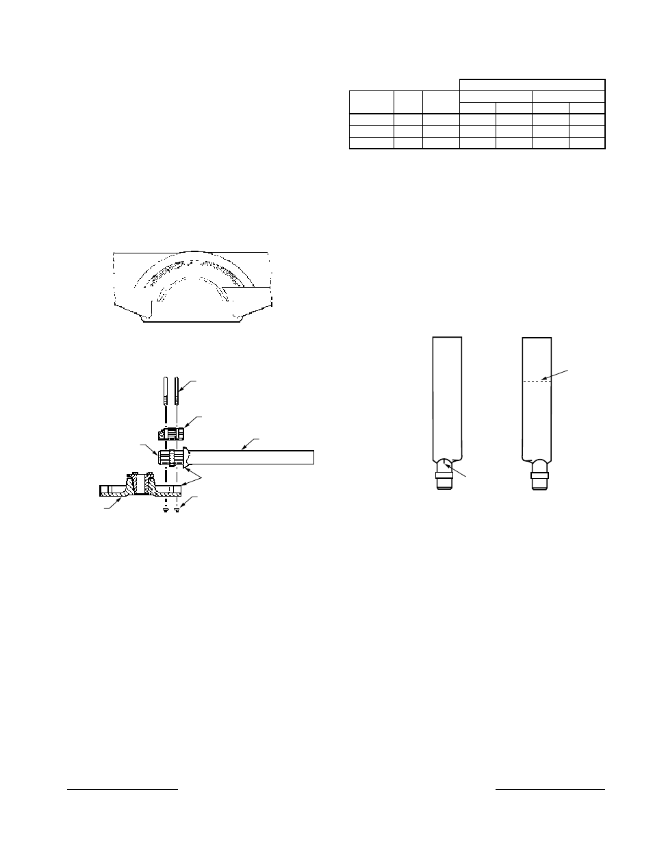
Angle.setting.index.on.shank.socket..Marked.
from.10°.through.50°..Each.mark.is.2°..
Figure 14. Angle Setting Markings
Elastic Stop Nuts
Index Marks
Blade
U-Bolts
Cap
Blade
Shank
Hub
Figure 15. Assembly Exploded View
Angle
Setting
Mark
Index
Mark
.
Inlet.Side.
Discharge.Side
Figure 16. Blades and Angle Setting Mark
Torque
Prop
Size
Hub
Size
U-Bolt
Size
Aluminum
Fiberglass
Ft-lb
N-m
Ft-lb
N-m
54.-.72
14
1/2”
20
27
30
41
81.-.96
18
3/4”
45
61
50
68
108.-.144
18
3/4”
45
61
50
68
Table 8. U-Bolt Torque for Aerovent Blades
Twin ciTy fan & blower | www.Tcf.com
5959 Trenton Lane N | Minneapolis, MN 55442 | Phone: 763-551-7600 | Fax: 763-551-7601