Twin City Fans With CE Mark - ES-2-06 User Manual
Page 5
5.
Twin.City.Fan.Engineering.Supplement.2-06
10..Mount.drives.as.follows:
.
a..Slip. (do. not. pound). proper. sheave. onto. cor-
responding. shaft.. CAUTION:. PLACING. FAN.
SHEAVE.ON.MOTOR.CAN.OVERSPEED.WHEEL.
AND.CAUSE.STRUCTURAL.FAILURE.
.
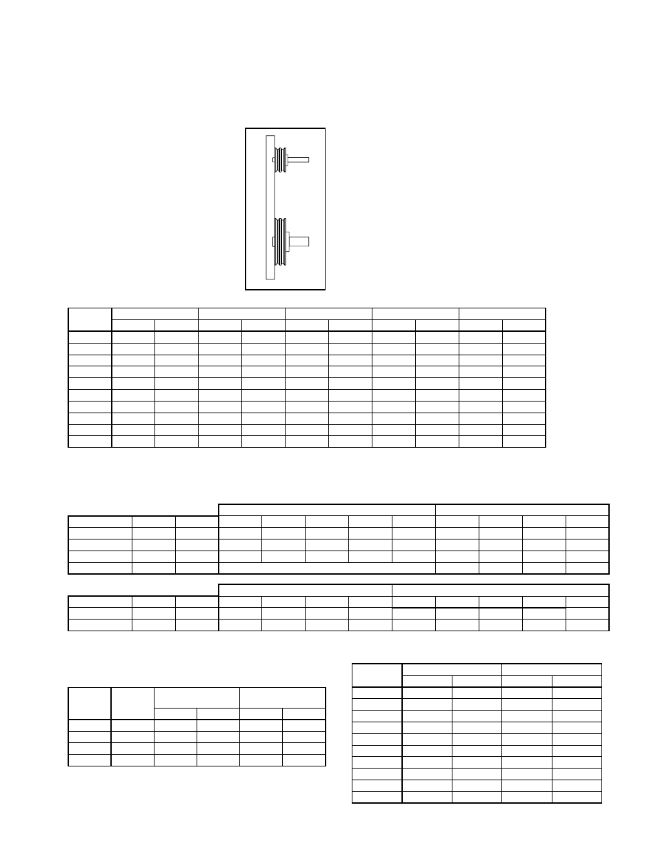
b..Align.sheaves.with.a.straight-
edge. extended. along. the.
perimeters. of. both. sheaves,.
just. making. contact. in. two.
places. on. outside. perimeters.
of. both. sheaves. (see. Figure.
5).. Parallel. alignment. should.
be. within. 5mm. per. meter.
of. center. distance.. Angular.
Misalignment. should. be. less.
than.1.degree.
.
c..Tighten.down.sheave.bolts.
.
d..Install. a. matched. set. of.
belts.. Adjust. belt. tension. as.
indicated.in.“Drive.Mounting”.
step.#3.
Size
Grade 2
Grade 5
Grade 8
Aluminum
Stainless
(Ft - lbs)
(N - m)
(Ft - lbs)
(N - m)
(Ft - lbs)
(N - m)
(Ft - lbs)
(N - m)
(Ft - lbs)
(N - m)
1/4 - 20
5.5
7.5
8
10.8
12
16.3
3.8
5.2
6.3
8.5
5/16 - 18
11
15
17
23
25
34
6.7
9.1
11
15
3/8 - 16
22
30
30
41
45
61
11.9
16
19
26
7/16 - 14
30
41
50
68
70
95
19
26
31
42
1/2 - 13
55
75
75
102
110
149
26
35
43
58
5/8 - 11
100
136
150
203
220
298
59
80
92
125
3/4 - 10
170
230
270
366
380
515
81
110
128
174
7/8 - 9
165
224
430
583
600
813
125
169
194
263
1 - 8
250
339
645
874
900
1220
184
249
287
389
1 1/4 - 7
500
678
1120
1518
1500
2034
336
456
523
709
.
e..Tighten.belts.to.proper.belt.tension..Record.the.
belt.tension.used..See.drive.mounting.section.for.
tensioning.instructions..Proper.tension.is.specified.
in.the.datasheet.included.with.the.fan.
11..Fans.that.have.motors.and.drives.mounted.at.the.
factory. are. trim. balanced. prior. to. shipment.. This.
is. not. possible. on. units. that. are. shipped. without.
motors. and. drives.. The. addition. of. drive. compo-
nents.in.the.field.can.create.unbalance.forces..Twin.
City. Companies,. Ltd.. recommends. final. balancing.
of.the.unit.after.the.drive.components.are.installed..
Failure.to.do.so.voids.the.Twin.City.Fan.Companies,.
Ltd..warranty.
12..Repeat.the.installation.checks.indicated.for.factory.
assembled. units. to. assure. proper. tightness. and.
alignment.of.all.components.
Bearing Installation
Bearings.are.only.to.be.field.installed.when.accompa-
nied.by.installation.instructions.from.the.bearing.manu-
facturer.. When. field. installation. is. required,. follow. the.
manufactures.instructions.carefully.to.install.bearings.
Table 1. Bolt Tightening Torque
METRIC SHAFTS
SET SCREW SIZE
LOCKING COLAR SCREW SIZE
Manufacturer
BRG ID
Units
M5
M6
M8
M10
M12
M4
M5
M6
M8
Dodge
S2000
N-m
-
-
17.8
35
57
-
-
-
-
Dodge
SCAH
N-m
3.4
6.9
16
28
51
5.85
10.75
20.5
45
Dodge
SCMAH
N-m
3.4
6.9
16
28
51
5.85
10.75
20.5
45
SKF
SY
N-m
See.Below
4.2
7.4
Table 2b. Metric Set Screw Torque Specifications
SY BEARING DIAMETER
PB224 BEARING DIAMETER
Manufacturer
BRG ID
Units
12-35mm 40-45mm 50-65mm
70-100mm
25,30mm 35-50mm
55mm
60-80mm 90,100mm
SKF
SY
N-m
4.
6.5
16.5
28.5
-
-
-
-
-
Linkbelt
PB224
N-m
-
-
-
-
21
37
52
77
153
Table 2a. Bearing Cap Bolt Torque Specifications (see page 6)
Bolt
Size
Bushing
Type
Iron/Steel Hub,
Sheave
Aluminum
Hub
Ft - lbs
N - m
Ft - lbs
N - m
1/4 - 20
H
8
11
8
11
5/16 - 18
P,.B
17
23
13
18
3/8 - 16
Q,.R
30
41
24
33
1/2 - 13
S
70
95
-
-
Table 3. Browning Split Taper Bushing Tightening Torque
Table 2c. IP Set Screw Torque Specifications (see page 7)
Set Screw
Size
Steel Set Screws
Stainless Set Screws
Ft - lbs
N - m
Ft - lbs
N - m
1/4 - 20
5.5
7.5
5.8
7.9
5/16 - 18
11
15
11
15
3/8 - 16
22
30
19
26
7/16 - 14
30
41
28
38
1/2 - 13
55
75
42
57
5/8 - 11
100
136
82
111
3/4 - 10
170
230
115
156
7/8 - 9
165
224
-
-
1 - 8
250
339
-
-
1 1/4 - 7
500
678
-
-
Table 4. Set Screw Tightening Torque (other than bearing
set screws)
Figure 5.
Sheave Alignment