Twin City Panel Fans & Power Roof Ventilators - ES-200 User Manual
Panel fans & power roof ventilators, Es-200, Introduction
Introduction
The purpose of this manual is to provide instructions
which supplement good general practices when installing
or operating fans made by TC Axial. It is the responsi-
bility of the purchaser to provide qualified personnel
experienced in the installation, operation and mainte-
nance of air moving equipment.
Always follow good safety practices when installing,
maintaining and operating your air moving equipment. A
variety of safety devices are available. It is the user’s
responsibility to determine adequate safety measures
and to procure the required safety equipment.
Shipping and Receiving
All TC Axial products are carefully constructed and
inspected before shipment to insure the highest stan-
dards of quality and performance. When received, all
components should be compared to the bill of lading or
packing list to verify that the proper unit was received.
Each unit should be checked for any damage which may
have occurred in transit. Any damage should be report-
ed immediately to the carrier and the necessary damage
report filed.
Unit Storage
If fan installation is to be delayed, store the unit in a
protected area. Protect the fan and motor bearings from
moisture and vibration (or shock loading). For extended
storage, wrap entire unit in plastic.
Installation
Panel Fans
Panel fans can be installed a number of different ways.
See Figure 1 for typical installation arrangements. If
dampers are used, they should be installed first. Then
the panel can be mounted and the motor wired.
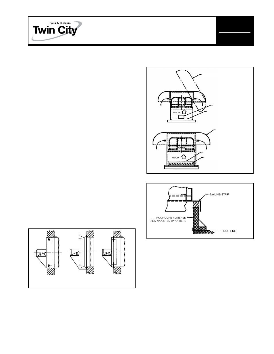
Power Roof Ventilators
See Figure 2 for typical installation arrangements and
Figure 3 for mounting to curb cap.
Opening and Closing Hood
For sizes 12" – 42", a one-piece hinged hood is stan-
dard. To lift the hood, remove the two bolts located
under the mushroom cap and prop the hood up with
the supplied safety rods. Push and lock into place. A
screw is installed at the end of the pin side of the hinge
in the hood angle to prevent accidental removal of the
hood. To close the hood, replace the bolts to lock in
place.
For size 48", a one-piece bolted hood connects
directly to the fan stack. To lift the hood off the unit,
remove the bolts located under the mushroom cap.
For sizes 54"–72", a two-piece bolted hood connects
directly to the fan stack. To lift the hood off the unit,
remove the sheet metal bolts that connect the right and
left sides of the hood and then remove the bolts locat-
ed under the mushroom cap.
Access To Dampers
A bolted access door is standard to provide access to
dampers.
Access To Wheel
Depending on fan size, wheels can either be removed
through the access door with the fan still mounted in
the hood or the fan can be lifted out of the unit and
the wheel removed.
Figure 1. Typical Panel Fan Installation Arrangements
Figure 2. Typical Power Roof Ventilator
Installation Arrangements
ReceSS
SURFace MoUnt
SURFace MoUnt
MoUnt
WIth Wall Box
WIth angle FRaMe
HINGED HOOD
BOLTED HOOD
SIZE 12" – 42" ACCESS
DOOR FOR INSPECTION
SIZE 48" – 60"
ACCESS DOOR FOR DAMPER
REMOVAL
SAFETY SCREEN STANDARD.
OPTIONAL DAMPER NOT SHOWN.
OPTIONAL DAMPER
Figure 3. Mounting Roof Ventilator to Curb Cap
eS-200
January 2000
Panel Fans & Power Roof Ventilators
InStallatIon, oPeRatIon & MaIntenance ManUal