Triner Scale 600-E Series User Manual
Page 12
Page 2-4
clearly marked (see fig. 2-3 for System Block Diagram). Place stainless steel platter
back onto the scale. Turn the scale on with the on/off switch located on the remote
keypad.
5. Remove the stainless steel top and disconnect all cables from the control module. Place
the scale base in the location provided (between ticket counters).
6. Center the frame in the opening. Adjust the leveling legs so that the scale base is in a
level position. Tighten the locknuts on the leveling feet.
7. Use the Scale Anchor Holes at each side of the lower frame (see fig. 2-5) to secure the
scale base in place with the eight (8) anchor bolts provided.
8. Attach the kick plates to the front and rear side of the lower frame. The kick plates
attach with Velcro so that they can be easily positioned and compensate for varying
height and level conditions.
9. The scale base must be grounded with the lead attached to the top frame. The center
screw on an electrical outlet or a metal conduit is usually suitable. Leave some slack in
the wire. Do not pull the wire tight because it can negatively affect weighing
performance.
2.4
Scale Base Installation (600-E Low Profile Style)
1. Remove the stainless steel platform cover by lifting it straight up. Remove the carton(s)
of electronics and verify that all components are present (see table 2-1).
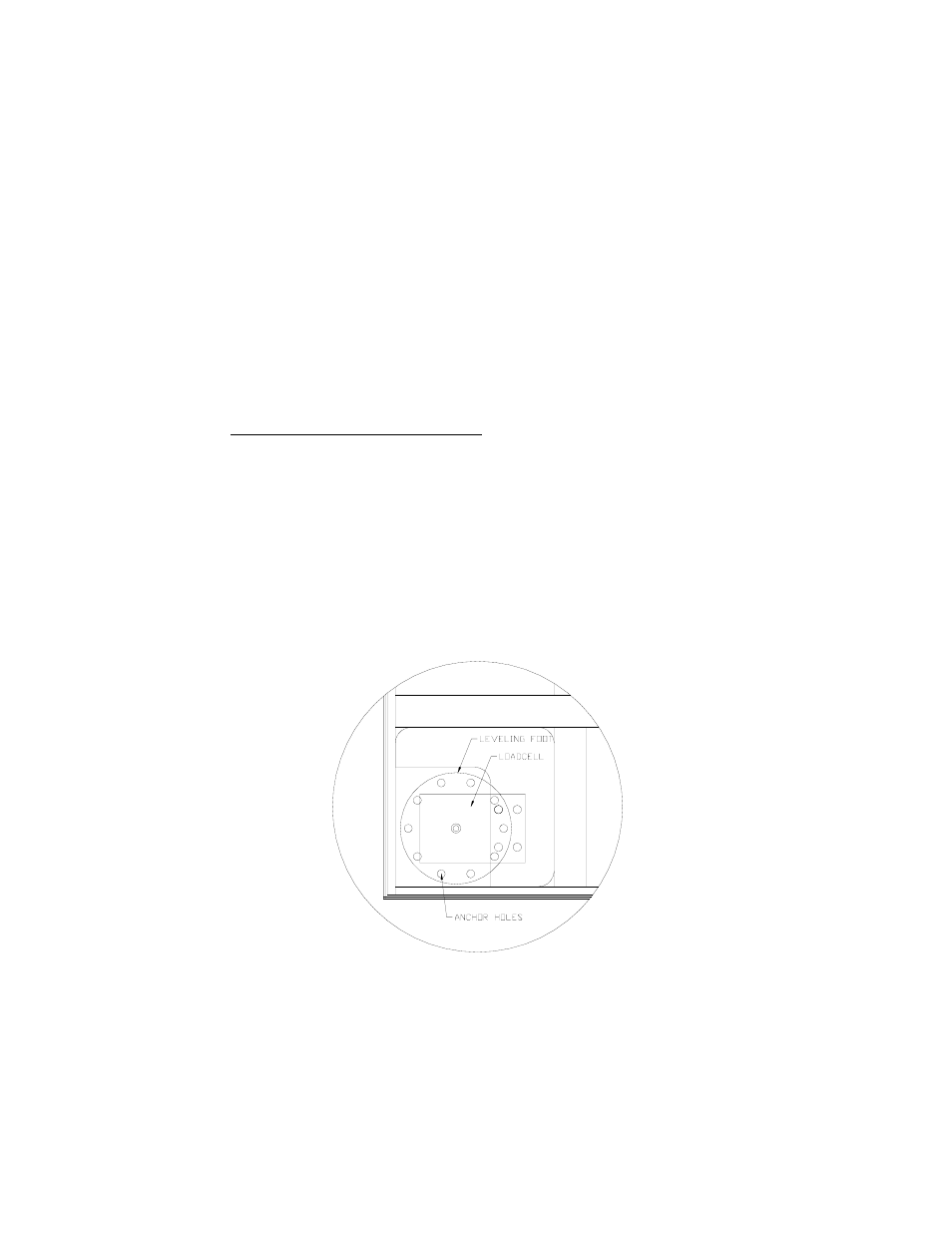
2. Locate the four (4) Leveling Feet. Remove the ¼-20 jam nuts. Thread the leveling feet
all the way into the threaded load cell holes in all four (4) corners of the scale frame (see
fig. 2-6).
Fig. 2-6: Corner Detail