Top Flite Antares User Manual
Page 9
kind, since the right angles are important. At this
point, if you are going ahead with the VA" stabs, you
should trim Vis" off of each side of these ribs. We
would suggest that now is a good time to check and
make sure that these holes are properly spaced and
will fit. Locate four (4) Va" O.D. x TVie" brass tubes and
the two W dia. x 2%" M.W. stab joining wires. Tem-
porarily install the four tubes into the holes in the ply
stab root ribs and assemble these to the fin with the
joining wires. The fit should be smooth and non-
binding when moved up and down at the front of the
fin. All of this serves to confirm that the hole spacing
is correct—if it isn't, correct as needed.
3. Next, take one of the 1/8" O.D. stab tubes and slip the
1/8" I.D. wheel collar over one end. As shown on the
plans, mark the location of the wheel collar's set-
screw hole, r e m o v e t h e c o l l a r a n d f i l e o r g r i n d a notch
into and through the wall of the tube large enough to
let the set-screw pass, when tightened. Carefully
clean-out any metal "flash" on the inside and outside
of the tube, re-install the collar and test fit the set-
screw for clearance. Once satisfied, apply a small
amount of thick CA adhesive to the collar tube joint.
This is your one and only stab-locking tube (see stab
plan).
4. Cut or route-out a slot in one of the rear E-2's to accept
the wheel c o l l a r — t r i a l - f i t to be sure. Leaving the tube
and collar in place in the E-2 part, fit and hold two of
the 1/16" balsa laminates in place with your fingers,
press firmly with your fingers to create the collar's
indention on the inside of each skin. "Scoop-out"
balsa carefully from the indented areas, thus leaving
clearance for the collar. In the bottom skin, carefully
make a 1/8" hole for the set-screw.
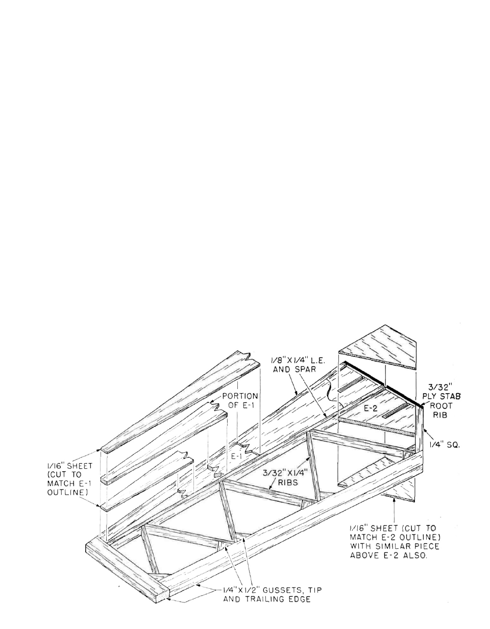
5. Assemble the stabs directly over the plans starting
with accurately locating and pinning in place the 1/8"X
1/4" upright "spar". Assemble the rest of the stab
structure as shown being careful to not get glue into
the joiner tubes. Be sure to use epoxy to secure the
tubes into their respective slots and that these tubes
are laying flat.
6. When dry, remove the stabs from the plan and use
your sanding block to sand them flat. Next, hold them
together and "match" their outside shapes—you
want them identical. Before going any further, trial-fit
the stabs to the fin. You will have to trim a little of the
length of the joiner wires to get the stabs to fit flush
with the fin sides as we have left these a little longer
for fitting purposes. What you're looking for during
this trial-fit is that the two stabs sit at 90° to the fin
sides and that their roots are flush with the fin sides
as well. Remove the stab halves and the joiner wires.
File or grind a small "flat" on one end of the rear
joiner wire for the set screw to bottom-out on when in
place—re-install and test-fit, including the set-screw.
Once satisfied, remove all of the components from
the fuselage.
7. As with the rudder, use your sanding block and 120
grit sandpaper to carefully bring the stabs down to
the cross sections shown. Note that what you are
trying to achieve here is a symmetrical airfoil. Also
9