Top Flite Antares User Manual
Page 4
with the top edges of the fuselage sides—MAKE A
LEFT AND RIGHT FUSELAGE SIDE.
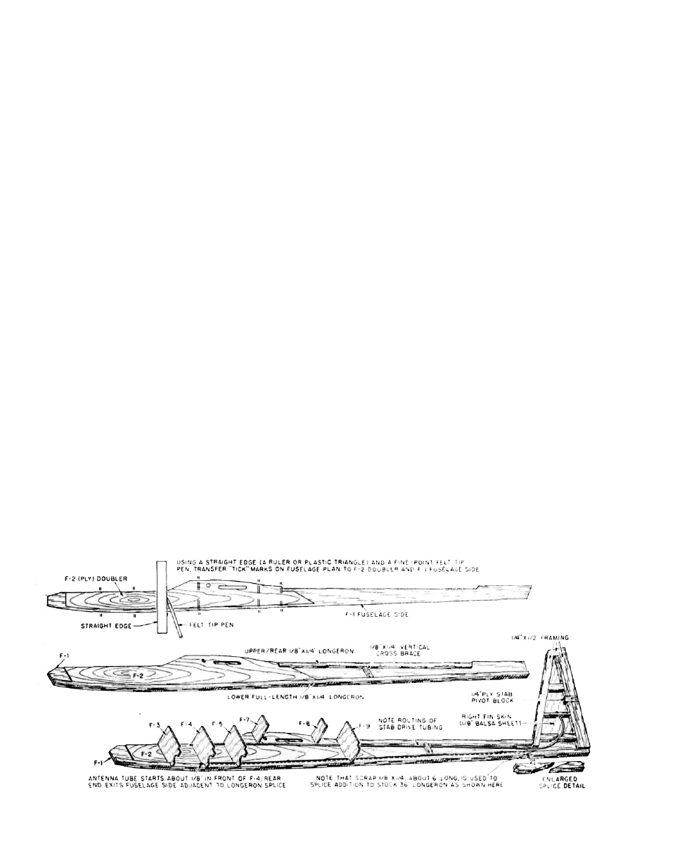
2. Using the 1/8" x 1/4" x 36" balsa stock supplied, glue the
bottom fuselage longerons in place, starting at the
front of the F-2 doubler, pinning and gluing as you
work aft. Note that you will need to add an additional
6" of this longeron stock at the rear to complete to full-
length bottom longeron.
3. Cut and glue the top rear 1/8" x 1/4" balsa longerons in
place. Note that this longeron extends from the back
of the F-9 former position to the leading edge of the
fin location where it is cut on an angle to match the
fin.
4. Using a sharp pencil and a straightedge, mark the
locations of all fuselage formers; F-3, F-4, F-5, F-7, F-8
and F-9, including the location of the rear 1/8" x 1/4"
fuselage uprights, behind former F-9—mark these
locations on the right fuselage side. Holding the left
fuselage side to the right, so that they are accurately
matched, transfer the former locations to the left
fuselage side.
5. You will now need to drill an angled hole in the left
rear fuselage side for the outer plastic rudder cable
housing. Note its location on the plans and its dis-
tance from the rudder hinge line. Don't deviate from
this location because if it is too far forward, the rudder
cable may be prone to "bending" during'operation
and too far aft will mean that you can't get full rudder
throw. Repeat this process on the right fuselage side
for the internal antenna tube — first check the length
of your antenna to be sure that at least 1" of it will
protrude from the tube at the rear. A sharpened piece
of 1/8" dia. brass tubing works very well for drilling
these holes at the right angles and cleanly.
6. Pin, tape or lightly spot glue the two fuselage sides
together, with their outer surfaces touching — align
them to each other very carefully. Using a sanding
block, sand their outer edges to match them identi-
cally. While the sides are still together, carefully
match the main wing tube holes and access slots. We
have purposely made the main wing tube holes a
very tight fit, work carefully to open them up enough
to accept a length of 11/32" O.D. brass tubing (3 pieces
supplied in the kit). The main wing tube holes must
line-up accurately.
7. Remove both W-1 ply wing root ribs and both F-10
f u s e l a g e root ribs c a r e f u l l y f r o m their sheets.
Remove the main wing tube holes from each of the
ribs and access slots from the F-10 ribs—use a hobby
knife to assist you. Take one of the F-10 ribs and locate
the identification at the back. Drill a 1/8"dia. hole in this
rib, at 90° to its surface—this rib is now your "drill
guide" for the rest of the ribs. Insert one of the main
wing wire tubes into the hole in the "drill guide" rib,
letting one end of it extend out from the rib about 1/16".
Now drill the 1/8" dia. hole needed in the remaining
F-10 and W-1's, by placing the rib onto the wing wire
tube, lining up the rib to be drilled with the "drill
guide" rib and drilling the hole—repeat this process
until all four ribs have accurately aligned and drilled
holes. Use the same procedure on the now matched
fuselage sides; insert one of the main wing wire
tubes into the hole in the fuselage side, slide an F-10
rib onto the tube and down flat against the outside of
the fuselage side, position as shown on the plans and
drill the 1/8" dia. hole. Repeat this process with the
other fuselage side.
8. Remove ply tailskid from its sheet. Position the tail-
skid in place on one of the fuselage sides, as shown
on the plans. Mark its forward edge location on the
bottom, rear longeron in pencil. With a single edge
razor blade, remove approximately 1/32" of the thick-
ness of the longeron, forward to the pencil mark —
this becomes half of the slot that the tailskid will fit
into. Repeat this process to the other fuselage side to
create the 1/16" wide tailskid slot.
9. Lay the right fuselage side on your work surface in
front of you with the inside facing you. "Take one of the
servos that you plan to use for either the stabilizator or
rudder and position it on the fuselage side between
the F-4 and F-5 former locations. Note the position of
the output arm. With a pencil, mark this location onto
the inner fuselage side. Note on the plans and cross-
sections that both the stab and rudder outer cable
housing tubes are positioned aft, through formers F-5
4