Top Flite TOPA0712 User Manual
Page 34
34
❏
5. Measure and set the low rate elevator throws and
the high and low rate throws for the rest of the control
surfaces the same way.
NOTE: The throws are measured at the widest part of
the elevators, rudder and ailerons.
These are the recommended control surface throws:
EL
EV
A
T
OR
HIGH RATE
LOW RATE
5/8"
[16 mm]
12°
Up
5/8"
[16 mm]
12°
Down
7/8"
[22 mm]
16°
Up
7/8"
[22 mm]
16°
Down
5/8"
[16 mm]
10°
1- 3/4"
[44mm]
24°
2-1/2"
[ 64 mm]
36°
Half
Rate
Full
Rate
Up
5/8"
[16 mm]
10°
Down
7/8"
[22 mm]
14°
Up
7/8"
[22 mm]
14°
Down
1-1/2"
[38 mm]
17°
Right
1-1/2"
[38 mm]
17°
Left
2"
[51mm]
24°
Right
2"
[51mm]
24°
Left
R
U
DDER
AIL
E
R
O
NS
FL
APS
BALANCE THE MODEL (C.G.)
More than any other factor, the C.G. (center of gravity/
balance point) can have the greatest effect on how
a model fl ies and could determine whether or not
your fi rst fl ight will be successful. If you value your
model and wish to enjoy it for many fl ights, DO NOT
OVERLOOK THIS IMPORTANT PROCEDURE. A
model that is not properly balanced may be unstable
and possibly unfl yable.
At this stage the model should be in ready-to-fl y
condition with all of the components in place including
the complete radio system, engine, muffl er, propeller,
spinner and pilot. The fuel tank should be empty.
Measure the high rate elevator throw fi rst…
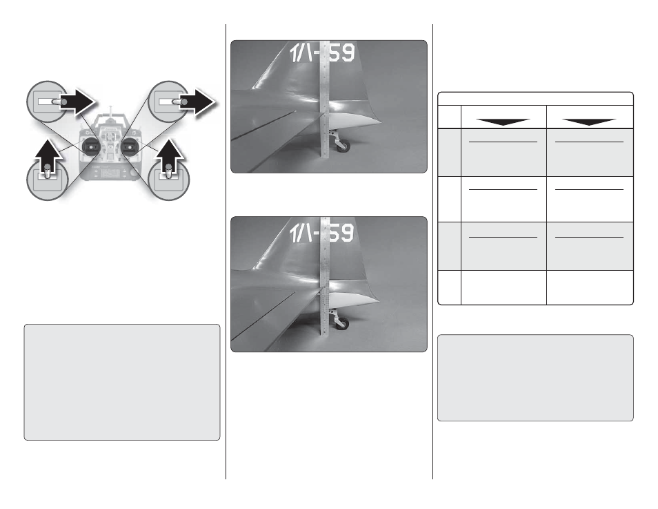
❏
2. Hold a ruler vertically on your workbench against
the widest part (front to back) of the trailing edge of the
elevator. Note the measurement on the ruler.
❏
3. Move the elevator up with your transmitter and
move the ruler forward so it will remain contacting the
trailing edge. The distance the elevator moves up from
center is the “up” elevator throw. Measure the down
elevator throw the same way.
❏
4. If necessary, adjust the location of the pushrod
on the servo arm or on the elevator horn, or program
the ATVs in your transmitter to increase or decrease
the throw according to the measurements in the control
throws chart.
FULL
THROTTLE
RUDDER
MOVES
RIGHT
ELEVATOR
MOVES DOWN
RIGHT AILERON
MOVES UP
LEFT AILERON
MOVES DOWN
4-CHANNEL RADIO SETUP
(STANDARD MODE 2)
❏
3. Make certain that the control surfaces and the
carburetor respond in the correct direction as shown in
the diagram. If any of the controls respond in the wrong
direction, use the servo reversing in the transmitter to
reverse the servos connected to those controls. Be
certain the control surfaces have remained centered.
Adjust if necessary.
SET THE CONTROL THROWS
To ensure a successful fi rst fl ight, set up your Zero
according to the control throws specifi ed in this
manual. The throws have been determined through
actual fl ight testing and accurate record-keeping
allowing the model to perform in the manner in which
it was intended. If, after you have become accustomed
to the way the Zero fl ies, you would like to change
the throws to suit your taste, that is fi ne. However,
too much control throw could make the model too
responsive and diffi cult to control, so remember,
“more is not always better.”
❏
1. Use a box or something similar to prop up the
bottom of the fuselage so the horizontal stabilizer and
wing will be level.