Connections – Toa C-CC574 PL User Manual
Page 29
29
12.1. Precautions When Installing the Camera
• Avoid install the camera cable in close proximity to other cables of electric products, such as fluorescent
lamps. Failure to do this could downgrade the picture quality.
• Installing the camera near the strong electric or magnetic field produced by television transmitting antennas,
motors or transformers could distort or shake the monitor screen. In such cases, install the cables in the
sheet steel cable piping.
• Before applying the power to the camera, be sure to complete all connections between the camera and
related equipment.
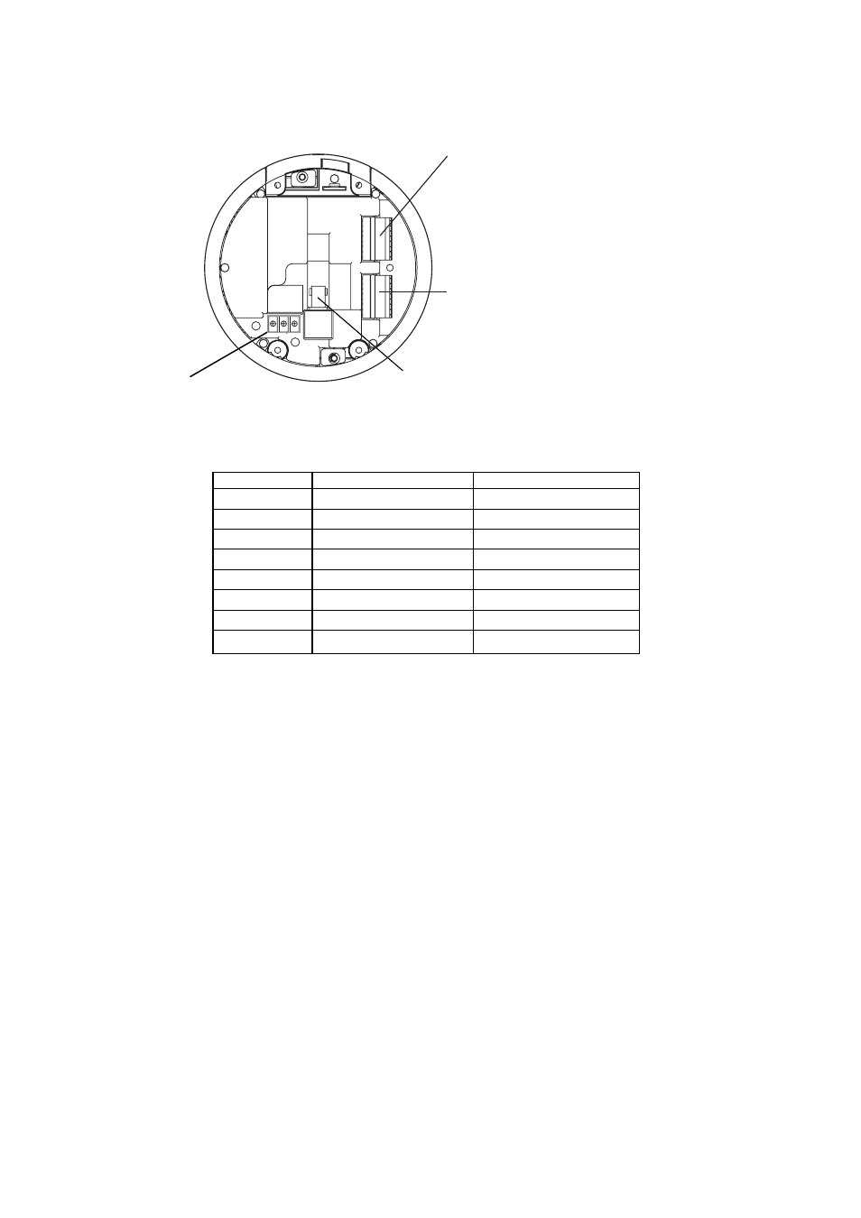
Connector 1 (CN1)
No. 1 – 5: Alarm Input/Output terminal
Connect to the sensor of no-voltage make contact
or the external equipment to be controlled using
the auxiliary contact output.
No. 6 – 8 Camera control terminal
When controlling the camera using the RS-485
communication line, connect to the cable from
remote controller or other camera.
Connector 2 (CN2) (C-CC564 C-CC574 only)
No. 1 – 8: Alarm input/Output terminal
Connect to the sensor of no-voltage make contact
or the external equipment to be controlled using
the auxiliary contact output.
Video output
When controlling the camera using the RS-485
communication line, connect to the video input terminal
of multi-switcher or monitor.
Power input
Connect to the power supply.
Connector 1 (CN1)
Connector 2 (CN2)
GND
NC (Normally Close)
Alarm 3
COM
Alarm 2
NO (Normally Open)
Alarm 1
Alarm 8
AUX (Open Collector)
Alarm 7
GND
Alarm 6
B (RS-485) (–)
Alarm 5
A (RS-485) (+)
Alarm 4
Terminal No.
(1)
(2)
(3)
(4)
(5)
(6)
(7)
(8)
12. CONNECTIONS