Toa RS-442 User Manual
Switch board rs-442, Installation manual, General description
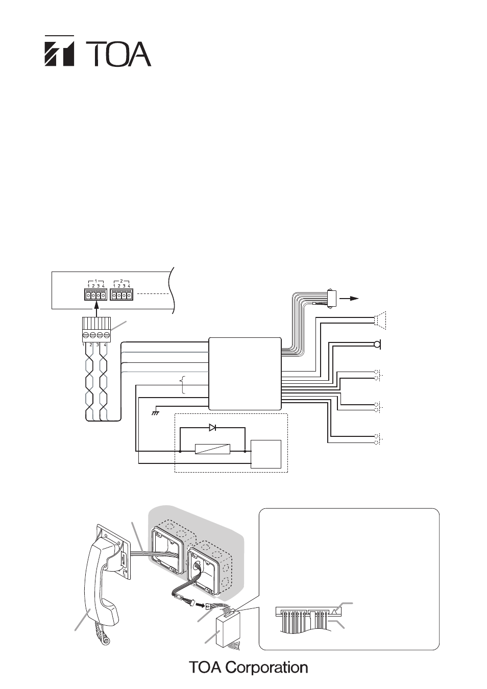
4P removable terminal plug
(supplied with the N-8400RS)
N-8400RS Substation interface unit
To line 2 (Red)
Two pairs of
twisted pair cable
To handset
(refer to the following figure)
Frame
ground
Switch input for
the call button 3
(momentary)
Switch input for
the call button 2
(momentary)
Switch input for
the call button 1
(momentary)
To line 1 (Brown)
To line 4 (Yellow)
(Green)
(Blue)
(Black)
RS-442
To line 3 (Orange)
8 Ω speaker output
(Red) +
-
(Black)
(Gray)
(White)
(Brown)
(White)
(Blue)
(White)
*Open collector output: 24 V DC, Max. 30 mA
Control output *
External
power supply
Relay
Diode
24 V DC
GND
+
-
Microphone
INSTALLATION MANUAL
SWITCH BOARD
RS-442
Thank you for purchasing TOA’s Switch Board.
Please carefully follow the instructions in this manual to ensure long, trouble-free use of your equipment.
1. GENERAL DESCRIPTION
The RS-442 is a Switch board to be connected to the N-8400RS 4-wire system Substation Interface Unit.
It is equipped with 1 microphone input (with a microphone unit), 3 switch inputs for call buttons, and 1 speaker
output, enabling you to make a switch panel suitable for applications.
By assigning a different master station as a calling destination to each Call button, you can call one of them
and make a conversation.
2. CONNECTION
RS-442
Handset joint
cables
Handset cables
Wall surface
RS-481
RS-442 (Bottom)
Note
When using the RS-481 Option handset, cut the
jumper wire next to the handset joint cables on
the circuit board as illustrated below.
If not cut, sound comes out from the RS-442's
speaker and returns back to the handset’s
microphone, resulting in acoustic feedback.
Jumper wire
Handset joint cables
[RS-442 and RS-481 connections]
Note
Cut out unused wires to avoid short-circuiting.