Toa S5 Series Installation User Manual
Page 25
Page 24 – S5 Wireless Microphone Installation Guide Rev 1.5
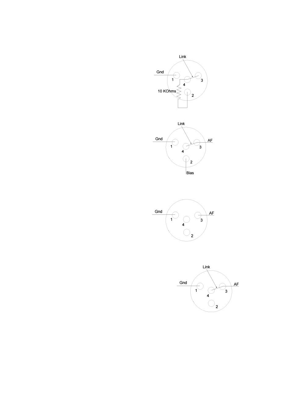
Wiring for Mini-XLR Flying Socket
2 Wire Mic
Pin 1: Ground
Pin 2: 5 V
Pin 3: AF
Pin 4: Internal AF load resistor
Link pins 3 and 4 and add a 10 KΩ bias
resistor as illustrated
3 Wire Mic
Pin 1: Ground
Pin 2: 5 V
Pin 3: AF
Pin 4: Internal AF load resistor
Link pins 3 and 4 as illustrated
Hi Impedance Guitar/Instrument
Pin 1: Ground
Pin 2: 5 V - Not connected
Pin 3: AF Hi Z
Pin 4: Not connected
Connect screened cable to pin 1
ground and pin 3 AF Hi-Z
Lo Impedance Microphone (No Phantom)
Pin 1: Ground
Pin 2: 5 V - Not connected
Pin 3: AF Hi-Z
Pin 4: Internal AF load resistor
Link pins 3 and 4 and connect screened cable to
pin 1 ground and pins 3 and 4 as illustrated