Internal wiring diagram, Line array speaker sr-h2l and sr-h2s, Line array speaker sr-h3l and sr-h3s – Toa SR-EP3 User Manual
Page 9
9
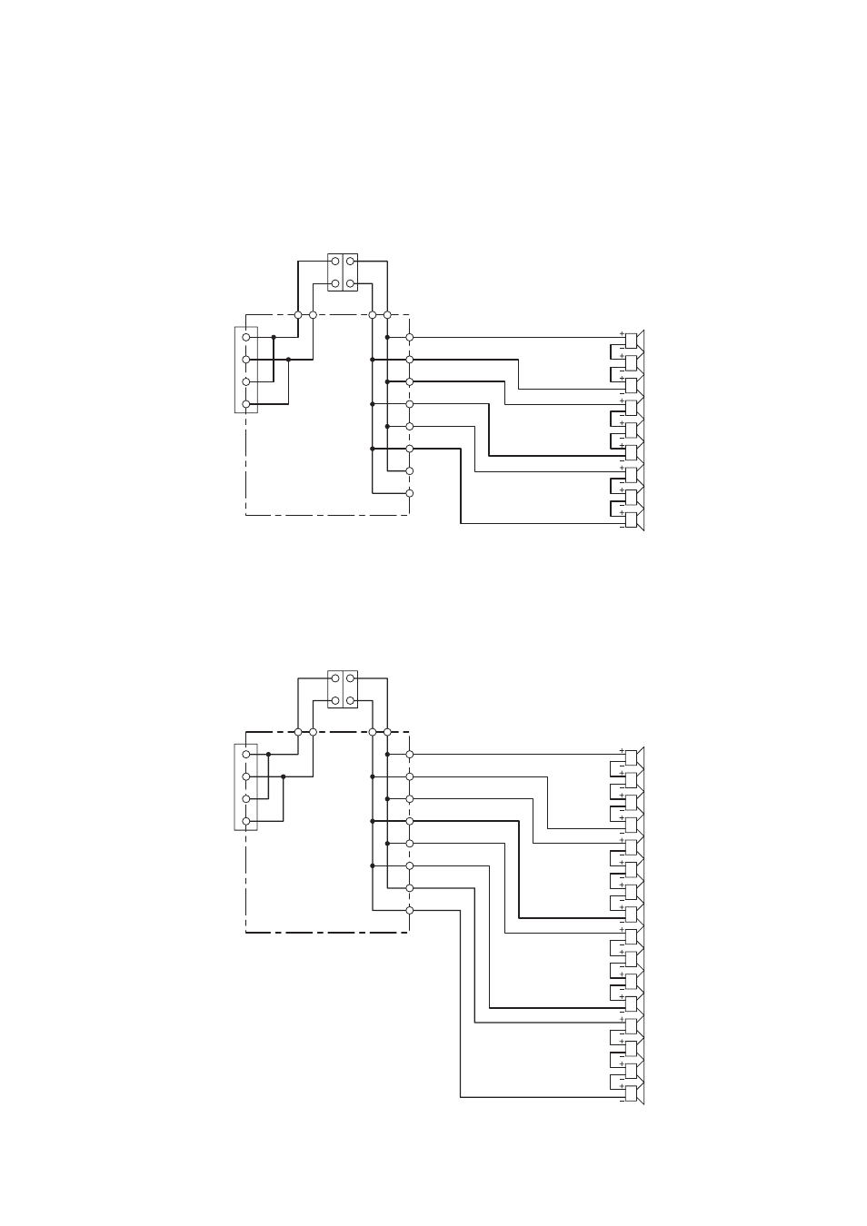
6. INTERNAL WIRING DIAGRAM
When shipped from the factory, the speaker is internally connected as shown below.
Since two pairs of “+” and “–” input terminals are parallel-connected internally, they can be used for parallel
connection to a second speaker.
6.1. Line Array Speaker SR-H2L and SR-H2S
OUT +
IN +
OUT -
OUT +
OUT -
OUT +
OUT -
OUT +
OUT -
IN -
IN +
IN -
PCB
Speaker unit
Interlocked connectors for the matching transformer
Input terminal
6.2. Line Array Speaker SR-H3L and SR-H3S
OUT +
IN +
OUT -
OUT +
OUT -
OUT +
OUT -
OUT +
OUT -
IN -
IN +
IN -
PCB
Speaker unit
Interlocked connectors for the matching transformer
Input terminal